The sheet metal fabrication process turns a flat metal sheet into a finished part through seven stages: design and DFM review, cutting, forming and bending, joining, hardware insertion, finishing, and final inspection. Each stage feeds the next, and the order isn’t arbitrary — get the sequence wrong, and you either weaken the part or pay to redo it. Understanding the full flow is what lets you send a fabricator a drawing that quotes cleanly and comes back right the first time.
Most guides on this topic read like a glossary — a list of processes with no sense of what actually happens first or why. This one follows the real production path a part takes on the shop floor, from the moment a drawing lands to the moment the finished part is boxed. Along the way it covers the cutting methods and their trade-offs, why hardware is installed before coating rather than after, the tolerances each stage can hold, and where cost is won or lost.
The sequence below is the one Manufyn’s sheet metal fabrication service runs every day. Manufyn is an ISO 9001 certified, strictly in-house manufacturer in Pune, India, so this is written from the floor where the parts are actually made — not a reseller’s summary of it.
The 7 Steps of the Sheet Metal Fabrication Process at a Glance
Before the detail, here’s the full sequence in one view — what happens at each stage and why it sits where it does in the order.
| Step | Stage | What happens |
|---|---|---|
| 1 | Design & DFM review | Drawing checked for manufacturability before anything is cut |
| 2 | Cutting | Flat blank cut from the sheet by laser, punch, or shear |
| 3 | Forming & bending | Flat blank bent into its 3D shape on a press brake |
| 4 | Joining | Parts welded, riveted, or fastened into an assembly |
| 5 | Hardware insertion | Studs, standoffs, and nuts pressed in — before finishing |
| 6 | Finishing | Powder coat, anodize, plate, or passivate for corrosion and appearance |
| 7 | Inspection & dispatch | Dimensional check, documentation, and packing |
Step 1: Design and DFM Review
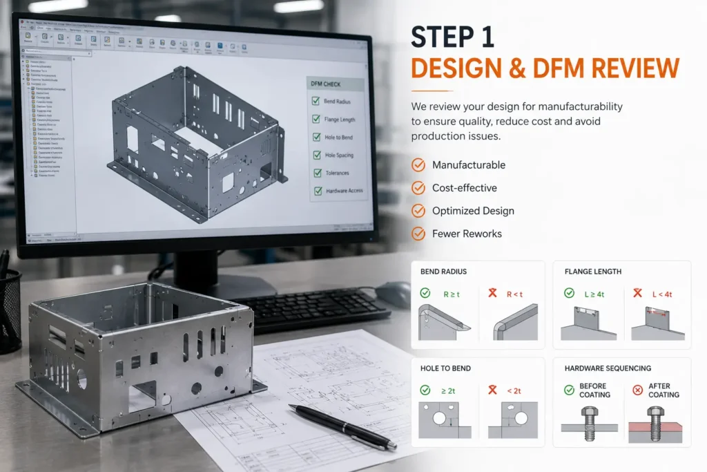
Fabrication really begins before any metal is cut. A design-for-manufacturability review checks the drawing against what the machines can actually hold, catching costly problems while they’re still free to fix.
The review looks for the handful of issues that cause most rework: bend flanges shorter than about four times material thickness, holes placed too close to a bend line, tolerances tighter than the part’s function needs, and hardware sequenced after coating. Each of these is trivial to correct on a CAD file and expensive to correct in scrapped metal. A fabricator who flags them before quoting is saving you money you’d otherwise never see leave your account. The two design details that trip up the most incoming drawings are bend radius and hole placement — our bend radius guide and hole and slot placement guide cover both in full. Skipping DFM doesn’t remove these risks; it just moves the discovery to the worst possible moment, at incoming inspection.
Step 2: Cutting the Flat Blank
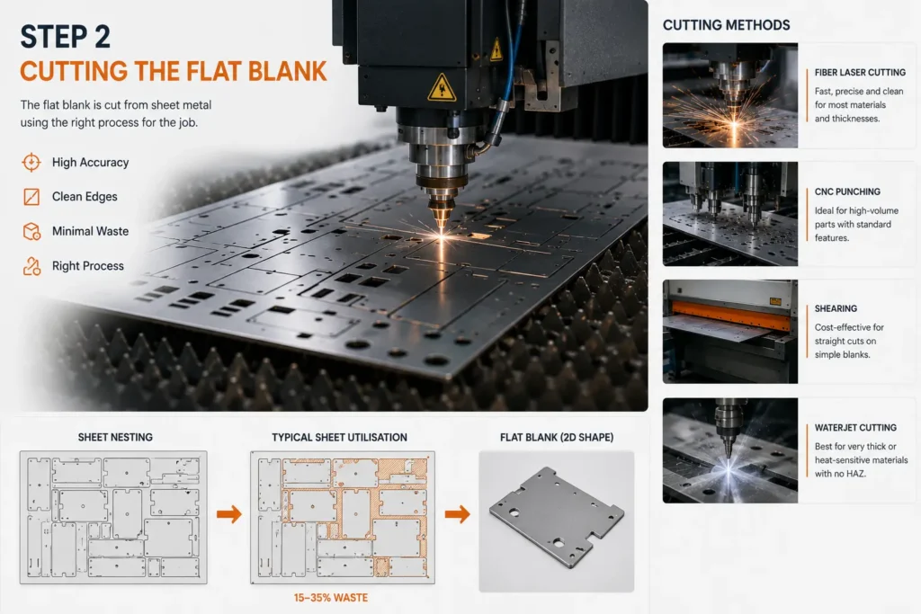
Cutting produces the flat blank — the 2D shape that later gets bent into the finished part. The method chosen sets edge quality, accuracy, and how much sheet gets wasted in the process.
The cutting method is a real decision, not a formality, and it’s usually driven by material, thickness, and edge-quality needs. Fiber laser cutting dominates modern fabrication because it’s fast, precise, and clean across most thicknesses; CNC punching suits high-volume repeat parts with standard features; shearing gives cheap straight cuts on simple blanks; and waterjet handles very thick or heat-sensitive material without a heat-affected zone. How parts are nested on the sheet matters too — good nesting keeps scrap to a workable range, but a typical layout still consumes 15–35% of the sheet as waste, which is why sheet utilisation shows up directly in your quote.
| Cutting method | Best for | Typical edge accuracy |
|---|---|---|
| Fiber laser | Most parts, thin to medium gauge, complex profiles | ±0.05–0.1 mm |
| CNC punching | High-volume parts with standard holes and features | ±0.1 mm |
| Shearing | Simple straight-line cuts, low cost | ±0.2 mm |
| Waterjet | Thick, reflective, or heat-sensitive material | ±0.1–0.2 mm |
For a deeper look at choosing between methods, see our guide to the types of sheet metal fabrication.
Step 3: Forming and Bending
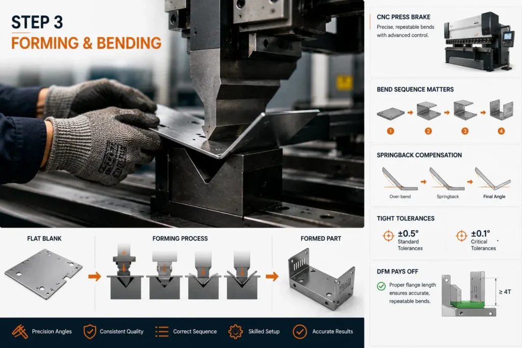
Forming turns the flat blank into a three-dimensional part. A CNC press brake bends the sheet to precise angles, and this is where a drawing becomes a real object.
Bending is the stage where fabrication skill shows most clearly. The press brake presses the blank into a die to form each bend, and the result depends on getting bend allowance, springback, and bend sequence right — every part has an order in which its bends must be made, because forming one flange can block access to another. Material fights back too: metal springs back slightly after bending, so the tooling over-bends to compensate, and the amount depends on the alloy and thickness. Modern press brakes hold bend angles to roughly ±0.5° on standard work and down to ±0.1° where a critical callout demands it. This is also where DFM from step one pays off — a flange too short to grip in the die simply can’t be bent accurately, which is exactly the kind of problem the review is meant to catch before the metal is cut. Our bend radius guide covers the rules that keep bends repeatable.
Have a drawing you want checked before it’s cut? Send it to Manufyn for a free DFM review and a firm quote within 24 hours — ISO 9001, strictly in-house, no minimum order.
Step 4: Joining and Welding
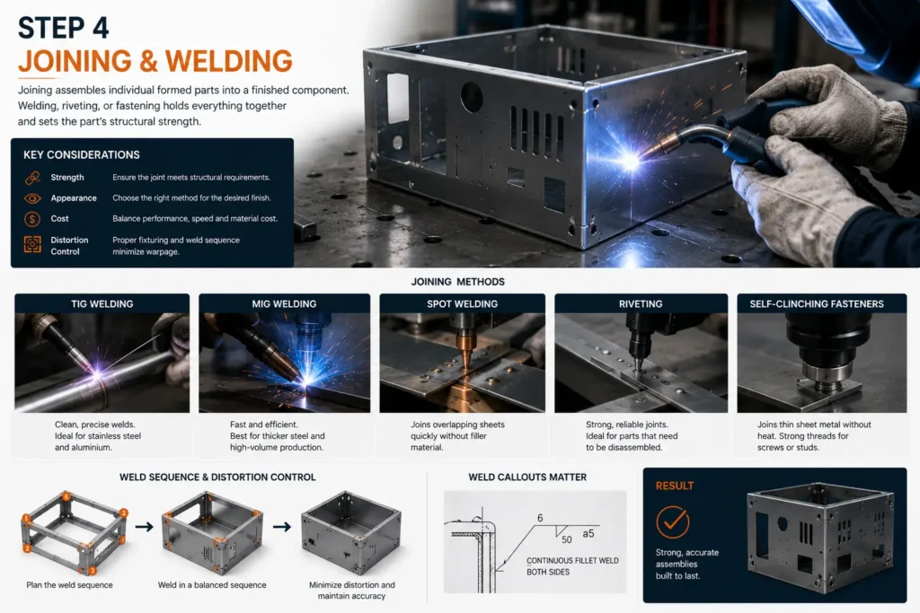
Joining assembles individual formed parts into a finished component. Welding, riveting, or fastening holds everything together and sets the part’s structural strength.
Not every part needs joining, but most assemblies do, and the method chosen affects strength, appearance, and cost. TIG welding gives the cleanest, most controlled welds and suits stainless steel and aluminium where cosmetics matter; MIG welding is faster and better for thicker steel and higher-volume work; spot welding joins overlapping sheets quickly without filler; and riveting or self-clinching fasteners join parts that may need to come apart later or can’t take welding heat. Welding introduces heat, and heat introduces distortion — a skilled fabricator manages the weld sequence and fixturing to keep the finished assembly flat and dimensionally true. How you call out welds on your drawing determines what you get back, which our welding design guide explains in detail.
Step 5: Hardware Insertion
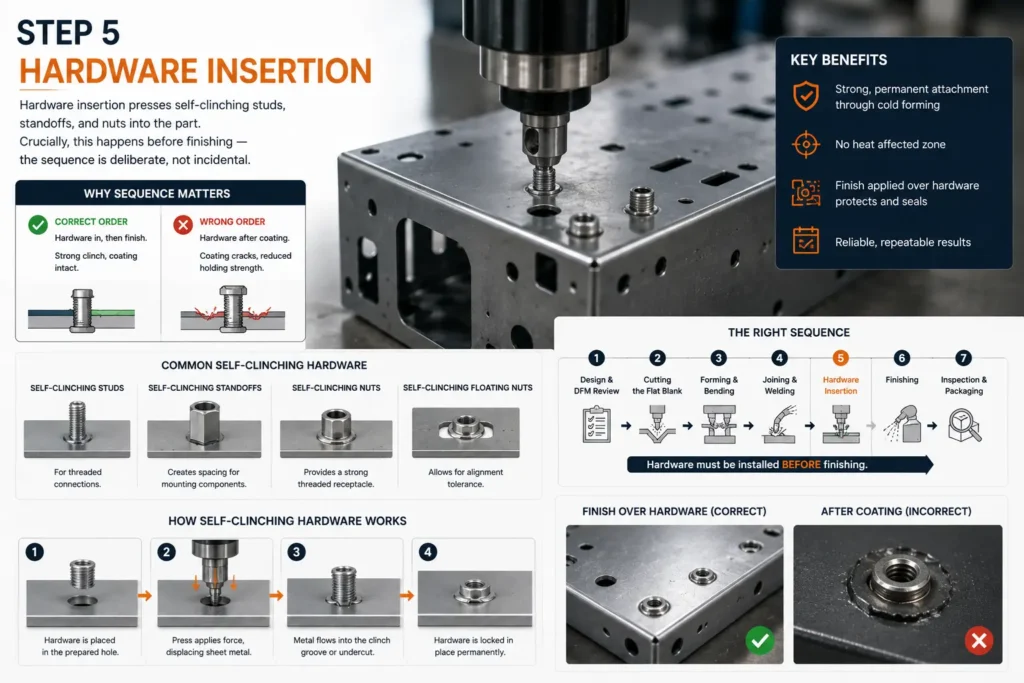
Hardware insertion presses self-clinching studs, standoffs, and nuts into the part. Crucially, this happens before finishing — the sequence is deliberate, not incidental.
This is the step most non-specialists get wrong, and it’s why it deserves its own section rather than a footnote. Self-clinching hardware works by cold-forming into the sheet, displacing metal to lock itself permanently in place. Install it before finishing and the clinch is clean and full-strength. Install it after coating and two things go wrong: the coating cracks around the insertion point, and the clinch grips a softer, coated surface that reduces its holding strength. The correct order — hardware in, then finish over it — is one of the clearest signals that a fabricator understands the full process rather than treating each step in isolation. It’s also exactly the kind of sequencing error a DFM review at step one is meant to prevent. Standard fastening approaches are covered in our fastening methods guide.
Step 6: Surface Finishing
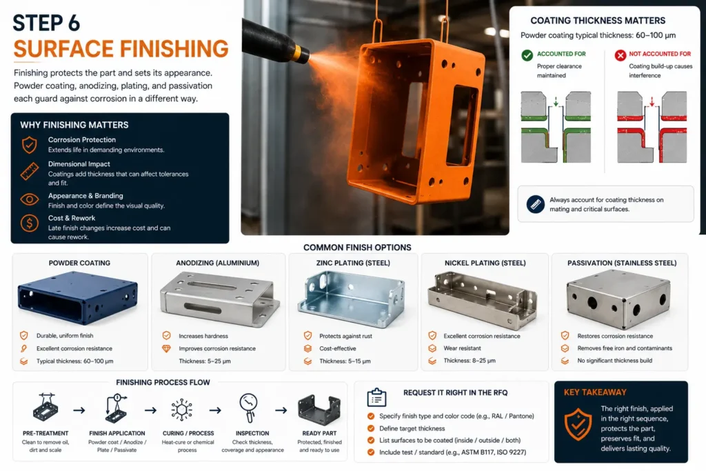
Finishing protects the part and sets its appearance. Powder coating, anodizing, plating, and passivation each guard against corrosion in a different way.
Finishing is more than cosmetic — it’s what decides how long the part survives in its environment, and it has a real dimensional consequence buyers often miss. Powder coating adds a durable, colored layer 60–100 µm thick, which is enough to turn a designed slide fit into an interference fit if it isn’t accounted for on mating surfaces. Anodizing suits aluminium and adds hardness and corrosion resistance; zinc and nickel plating protect steel; and passivation restores stainless steel’s corrosion resistance after fabrication. The finish, its color code, and its target thickness all belong in the original RFQ, because a finish requested after production has started costs more and can force rework. Which finish fits which material is covered in our sheet metal materials guide.
Step 7: Inspection and Dispatch
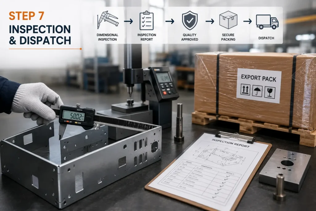
The final stage verifies the part matches the drawing before it ships. Dimensional inspection and documentation are what turn a finished part into proof it was made right.
The last step is where a real quality system separates itself from a shop that simply hopes the parts are right. A first article inspection report (FAIR) documents that the first piece meets every drawing dimension; batch inspection checks that production parts hold to spec; and material test reports and certificates of conformance provide traceability back to the raw material. For regulated work, this paperwork isn’t optional — it’s the difference between a part you can use and a part you can’t prove. Once inspection passes, parts are export-packed with customs documentation for shipment. A fabricator who provides this by default, rather than only when chased, is one whose process you can trust. Our guide on sheet metal fabrication tolerances explains what’s realistic to inspect against.
Why the Order of the Process Matters
The seven steps aren’t interchangeable — the sequence itself carries the engineering logic, and reversing any of it costs quality or money:
- DFM comes first because every problem is cheapest to fix before metal is cut
- Cutting precedes bending because you can’t accurately bend a shape you haven’t yet cut to size
- Bending precedes joining because formed parts are what get assembled together
- Hardware goes in before finishing so the clinch is clean and the coating stays intact
- Finishing comes near the end so it covers a completed, assembled part
- Inspection is last because it verifies the finished result, not a work in progress
Buyer takeaway: when a fabricator can explain why each step sits where it does, you’re talking to someone who runs the process rather than resells it. That’s the single clearest test of whether your parts are in capable hands.
How Manufyn Runs the Full Process In-House
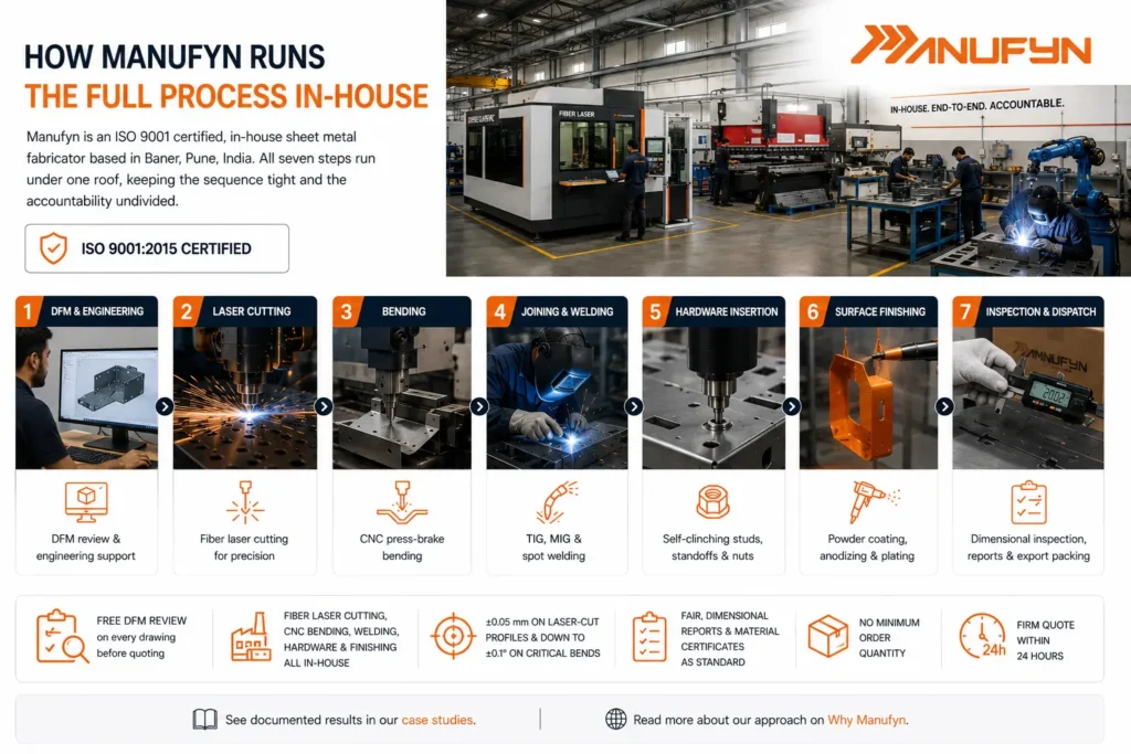
Manufyn is an ISO 9001 certified, strictly in-house sheet metal fabricator based in Baner, Pune, India — not a broker or marketplace. All seven steps run under one roof, which is what keeps the sequence tight and the accountability undivided.
Because cutting, bending, welding, hardware insertion, and finishing all happen in the same facility, parts never queue between outside vendors and no step is quietly subcontracted to a shop you never see. One engineering team carries your part from the DFM review through to the final inspection report, so a question about a bend or a finish gets answered by the people actually making it. That continuity is what prevents the quality drift that appears when each step lives in a different building.
- Free DFM review on every drawing before quoting
- Fiber laser cutting, CNC press-brake bending, welding, hardware, and finishing in-house
- ±0.05 mm on laser-cut profiles and down to ±0.1° on critical bends
- FAIR, dimensional reports, and material certificates as standard
- No minimum order quantity and a firm quote within 24 hours
See documented results in our case studies, or read more about our approach on Why Manufyn.
Ready to move a part through this process? Send your drawing to Manufyn — free DFM review, all seven steps in-house, no minimum order, and a firm quote in 24 hours.
FAQs
The sheet metal fabrication process has seven steps: design and DFM review, cutting the flat blank, forming and bending, joining and welding, hardware insertion, surface finishing, and final inspection and dispatch. Each step feeds the next, and the order is deliberate — hardware, for example, must go in before finishing to keep the clinch clean and the coating intact.
The first step is design and DFM (design-for-manufacturability) review, which happens before any metal is cut. It checks the drawing for issues like short bend flanges, holes too close to bends, and over-tight tolerances — problems that are free to fix on a CAD file but expensive to fix in scrapped metal.
The main methods are fiber laser cutting (fast and precise for most parts), CNC punching (high-volume standard features), shearing (cheap straight cuts), and waterjet (thick or heat-sensitive material). Fiber laser dominates modern fabrication because it’s accurate and clean across most thicknesses, holding roughly ±0.05–0.1 mm.
Self-clinching hardware cold-forms into the sheet to lock in place. If it’s installed after coating, the coating cracks around the insertion point and the clinch grips a softer coated surface, reducing holding strength. Installing hardware before finishing keeps the clinch full-strength and the finish intact — it’s a clear sign a fabricator understands the full process.
Laser cutting typically holds ±0.05–0.1 mm, standard bends around ±0.5°, and critical bends down to ±0.1° with proper equipment. Default to a general standard like ISO 2768-m for most dimensions and reserve tight callouts for assembly-critical features only — over-tolerancing every dimension is a common and avoidable cost driver.
Prototypes and first articles typically ship in 5–10 working days from drawing approval; production batches vary with volume and finishing. Finishing steps like powder coating and anodizing add time, and joining-heavy assemblies take longer than simple cut-and-bent parts.
A first article inspection report (FAIR) documents that the first produced part meets every dimension on the drawing. It’s a core quality record — especially for regulated work — and, alongside material test reports and certificates of conformance, provides traceability from the finished part back to the raw material.
Yes. Powder coating adds 60–100 µm of thickness, which can turn a designed slide fit into an interference fit on mating surfaces if it isn’t accounted for. Always specify the finish, color code, and target thickness in the RFQ so mating dimensions are adjusted before the part is made.
Have a question about your specific part? Send your drawing to our engineers — we respond within 4 working hours.
Have a sheet metal part to fabricate?
Get a free DFM review and a firm quote in 24 hours — all seven process steps run in-house, with no minimum order.
Talk to Manufyn