
CNC Prototype Setup Considerations: Workholding, Datums and Accuracy
A practical engineering guide to planning CNC prototype machining before the first tool enters the material.
Understand how drawing requirements, datum selection, workholding, machining sequence and inspection influence prototype accuracy, manufacturing cost and delivery.
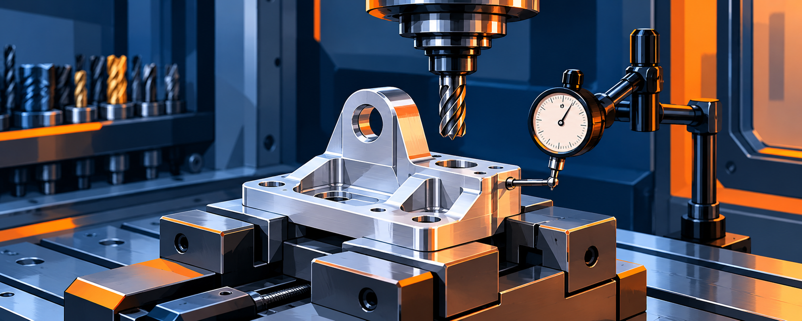
A CNC prototype can match its nominal CAD geometry and still fail inspection because the machining setup was not planned correctly. The part may move under cutting forces, thin walls may deform during clamping, or features machined in separate setups may lose their required positional relationship.
These problems are not always caused by the CNC machine or the programming. They can originate much earlier, when the manufacturing team decides how the component will be located, supported, oriented and measured.
This guide explains the setup decisions that engineers, CNC programmers, machinists and product development teams should evaluate before prototype machining begins.
1. What Are CNC Prototype Setup Considerations?
CNC prototype setup planning is the process of deciding how a component will be positioned, clamped, referenced, machined and inspected during manufacturing.
Before machining, the team should establish:
- The component’s functional datums and critical features.
- The machine and workholding method.
- The part orientation and CNC work coordinate system.
- The machining operations and number of setups.
- The tool access, clearance and support requirements.
- The inspection method for critical dimensions.
Setup planning is related to CAM programming, but the two are not identical. CAM defines tool movements. Setup planning establishes the physical conditions and references under which those toolpaths will operate.
Read the CNC Setup Planning Guide for a deeper explanation of repeatable machining setups.
2. Review the Engineering Drawing Before Setup
The setup plan should begin with the engineering drawing and CAD model, not with the machine vice. The drawing identifies the dimensions and feature relationships that the machining process must preserve.
What Should Be Reviewed?
- Material grade, temper and stock dimensions.
- Primary, secondary and tertiary datum references.
- Critical hole locations, bores, slots and mounting interfaces.
- Geometric dimensioning and tolerancing requirements.
- Surface finish and edge-break requirements.
- Thin walls, deep pockets and restricted tool access.
- Thread specifications and required engagement depths.
- Drawing revision and any customer-specific inspection requirements.
Identify which features are critical to fit, function or assembly. This helps determine which features should be machined from a common reference and which require additional control.
For example, if a mounting hole pattern must remain accurately positioned relative to a machined base, the setup plan should preserve that datum relationship throughout the operation sequence.
3. Datum Selection and CNC Work Coordinate Systems
Datum selection connects the engineering drawing to workholding, machining coordinates and inspection. A convenient surface is not automatically the correct datum; the reference should reflect the component’s functional requirements.
| Reference | Purpose | Example |
|---|---|---|
| Primary datum | Establishes the main reference plane. | Machined mounting face. |
| Secondary datum | Controls orientation relative to the primary datum. | Side face or locating surface. |
| Tertiary datum | Constrains the remaining required location. | End stop or locating feature. |
| CNC work coordinate system | Maps the selected part reference to machine coordinates. | A documented G54 work offset. |
The drawing datum, physical fixture locator and CNC work offset are related but distinct concepts. The setup documentation should explain how the physical part is located and how the machine coordinate system is established.
Where two features have a tight positional relationship, machining them in the same controlled setup can reduce the risk of re-alignment errors, provided the required tool access and rigidity are available.
Continue with Manufyn’s CNC Datum Selection Guide and CNC Work Coordinate System Guide .
4. Workholding: Select the Right Fixture
Workholding must locate the component consistently, resist cutting forces, provide tool clearance and avoid unacceptable deformation. A fixture that holds the part securely but distorts it can still produce inaccurate results.
| Workholding method | Typical application | Important consideration |
|---|---|---|
| Standard machine vice | Blocks, plates and prismatic components. | Part seating, jaw engagement and tool clearance. |
| Soft jaws | Irregular profiles and repeat prototype batches. | Jaw preparation and locating repeatability. |
| Fixture plate | Multiple features or repeated workpiece orientations. | Fixture access, rigidity and loading sequence. |
| Chuck or collet | Shafts and rotational components. | Concentricity, gripping length and surface protection. |
| Custom fixture | Complex geometry or recurring production requirements. | Fixture cost relative to expected production volume. |
Locating Is Not the Same as Clamping
Locators establish the position of the component. Clamps hold the component against those references. Increasing clamping force does not automatically improve location and can deform thin or flexible components.
Before releasing the setup, check:
- Whether the part sits firmly against its locating surfaces.
- Whether chips or burrs can prevent proper seating.
- Whether clamping forces can distort thin sections.
- Whether the fixture supports the component near cutting loads.
- Whether the complete toolpath clears the fixture and clamps.
Explore the CNC Workholding and Fixture Guide for additional workholding considerations.
5. How Many Setups Does a CNC Prototype Need?
The required setup count depends on the component geometry, feature accessibility, machine configuration, workholding and tolerance requirements. A single setup is useful when it provides adequate access and rigidity, but it should not be forced when doing so compromises the process.
| Strategy | When to consider it | Trade-off |
|---|---|---|
| Single setup | Required features are accessible from one orientation. | May simplify alignment, but can restrict access. |
| Multiple setups | Features are distributed across different faces. | Adds handling and datum-transfer considerations. |
| 4-axis machining | Indexed or rotary access is useful. | May reduce manual repositioning. |
| 5-axis machining | Compound angles or difficult approach directions are required. | Can reduce setups, but machine and programming costs matter. |
Every additional setup creates another opportunity for positional or angular variation. However, splitting an operation can improve rigidity, shorten tool reach and simplify inspection. The best strategy minimizes total manufacturing risk rather than simply minimizing the number of setups.
6. Material, Geometry and Tool Access
Material behavior and component geometry affect clamping, cutting forces, tool selection and dimensional stability. These factors should be considered before programming begins.
| Material or feature | Setup consideration |
|---|---|
| Aluminum alloys | Thin walls can distort under clamping and cutting forces. |
| Stainless steel | Cutting forces, heat and tool wear can affect process stability. |
| Alloy steel | Material condition and hardness influence tooling and machining strategy. |
| Nylon and engineering plastics | Elastic deformation, thermal expansion and moisture may influence measurement. |
| Deep pockets | Tool reach, deflection, chip evacuation and internal radii require review. |
| Thin walls | Support, clamping force and the material-removal sequence are important. |
| Angled or cross-drilled holes | Tool access, part orientation and positional control may determine setup count. |
A long, unsupported cutter can deflect while machining a deep pocket. This can affect dimensional accuracy and surface finish. Small internal radii may also require smaller tools and additional machining time.
A useful design-for-manufacturing review identifies whether difficult features are essential to part function before recommending changes. Any changes to controlled dimensions or interfaces must be approved by the design authority.
7. Plan the Machining Sequence Before Cutting
Machining order affects part rigidity, datum quality, material stress, tool access and the protection of finished surfaces. A setup plan should therefore be developed together with the machining sequence.
- Verify the material, stock dimensions and drawing revision.
- Establish a stable initial reference.
- Machine required datum surfaces.
- Rough the major material volumes while preserving adequate rigidity.
- Review whether stress relief or an intermediate inspection is necessary.
- Semi-finish and finish critical features in a controlled sequence.
- Complete secondary setups and required finishing operations.
- Deburr, clean and inspect the component.
This is a general planning sequence, not a universal program. The actual order must be adapted to the material, geometry, tolerances, stock condition and manufacturing method.
Read CNC Machining Sequence Planning for a more detailed discussion of operation sequencing and process strategy.
8. Tolerances and Inspection Planning
Not every prototype feature needs the tightest achievable tolerance. Requirements should reflect functional needs and product validation objectives.
| Feature | Inspection considerations |
|---|---|
| Mounting faces | Flatness, parallelism and perpendicularity where specified. |
| Holes and bores | Diameter, position, fit and datum relationships. |
| Shafts and rotational features | Diameter, runout and surface finish where required. |
| Threads | Thread specification, fit and engagement depth. |
| Pockets and slots | Width, depth, location and internal radii. |
Depending on the drawing and tolerance requirements, inspection may use micrometers, bore gauges, height gauges, thread gauges, surface-finish instruments or a coordinate measuring machine.
Define critical dimensions and inspection methods before machining begins. For international projects, agree in advance on any required inspection reports, material certificates and first article documentation.
9. How Setup Decisions Affect Prototype Cost
CNC prototype pricing includes more than cutting time. Programming, workholding, setup engineering, material preparation, inspection and logistics can be significant for low-quantity orders.
- Setup count: Additional orientations may increase labor and re-alignment effort.
- Fixture design: Custom jaws or fixtures can add upfront cost.
- Tool access: Deep cavities and small internal radii may require slower machining.
- Tolerances: Tight critical dimensions can require additional finishing and verification.
- Material: Grade, stock size and material-removal volume affect total cost.
- Quantity: Programming and fixture costs are spread differently across one part and a repeat batch.
- Delivery: Finishing, inspection, packaging and international freight affect the final delivered cost.
10. CNC Prototype Setup Checklist
Use this checklist during engineering review and before the first machining operation.
Drawing and Requirements
- Correct drawing revision and units confirmed.
- Material grade and stock dimensions confirmed.
- Functional datums and critical features identified.
- GD&T, threads and surface finish requirements reviewed.
- Inspection and documentation requirements agreed.
Workholding and Setup
- Locating surfaces are stable and accessible.
- Part seating and clamping force are appropriate.
- Fixture provides adequate support under cutting loads.
- Tool clearance and collision risks have been reviewed.
- Subsequent setups have a repeatable locating strategy.
Machining and Inspection
- Machine configuration and tool access are suitable.
- Machining sequence preserves required datum relationships.
- Work offsets and tool lengths are verified.
- Critical features have defined inspection methods.
- Final cleaning, deburring and documentation are planned.
Frequently Asked Questions
What should be considered before setting up a CNC prototype?
Review the drawing, material, datum references, workholding, cutter access, setup count, tolerance requirements and inspection method before machining begins.
How does workholding affect CNC prototype accuracy?
Workholding controls how consistently a component is located and supported. Poor seating, movement or excessive clamping force can cause positional errors or part deformation.
How many setups are required to machine a prototype?
The number depends on the geometry, accessible features, machine configuration and tolerance requirements. Some parts can be completed in one setup, while others need multiple orientations or multi-axis machining.
Is 5-axis machining always better for prototypes?
No. Five-axis machining can improve access to angled features and reduce repositioning, but a 3-axis or 4-axis machine may be more economical for simpler parts.
How can CNC prototype setup costs be reduced?
Improve cutter access, avoid unnecessary setups, use standard workholding where practical, clarify functional tolerances and plan inspection before machining begins.
What files are required for a CNC prototype quotation?
Typically, provide a 3D CAD model, dimensioned engineering drawing, material grade, quantity, tolerances, finishing requirements, inspection needs and delivery destination.
Related Manufacturing Case Studies
Engineering principles become more useful when connected to real manufacturing challenges. Explore Manufyn’s case studies to understand how machining process selection, inspection, delivery planning and supplier coordination affect prototype projects.