
Cable Integration for Electronics Manufacturing
A practical engineering and procurement guide to integrating cables, wire harnesses, connectors and electrical interconnections into electronic products, PCB assemblies and complete box-build systems.
Cable integration sits between electrical design and final product assembly. A cable may look simple, but its connector selection, termination, routing, bend radius, strain relief, shielding, polarity and testing can directly affect product reliability.
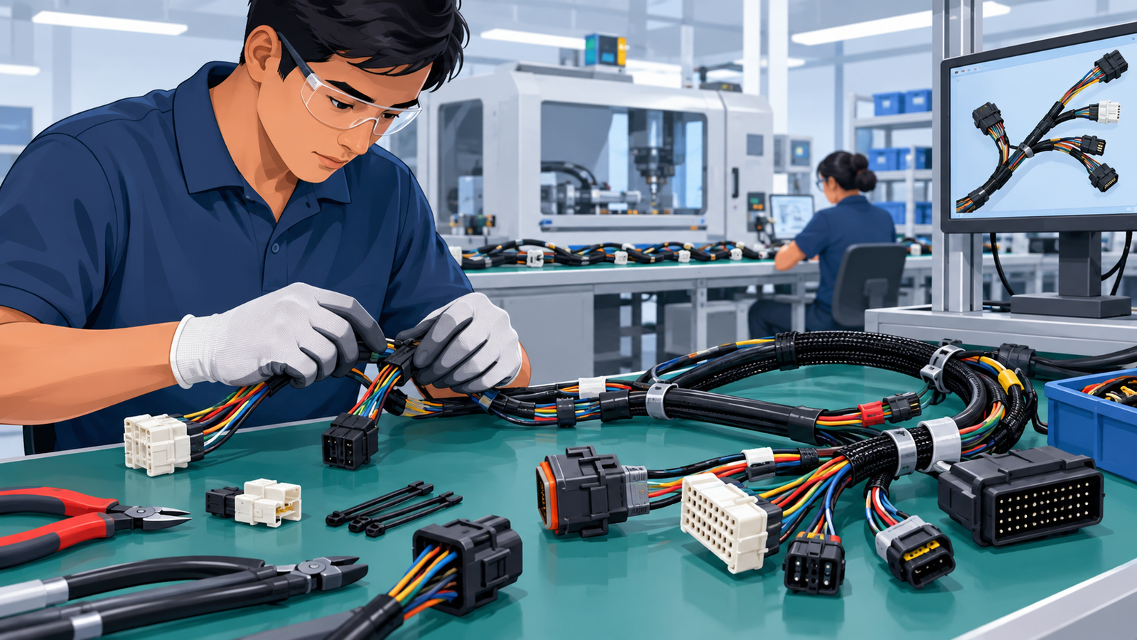
Why Cable Integration Matters in Electronics Manufacturing
Cable integration is the controlled installation and connection of electrical cables, wires, harnesses and connectors within an electronic product or subsystem.
It can include connecting a PCB to a display, power supply, sensor, motor, switch, battery, communication interface or another electronic assembly. In a larger box-build product, it can also include routing multiple harnesses through an enclosure and securing them to prevent interference, excessive bending or accidental disconnection.
Cable integration is common in industrial controllers, robotics, automation equipment, medical electronics, automotive modules, instrumentation, communication equipment, power electronics and connected devices.
For engineering teams, the challenge is ensuring that the electrical and mechanical requirements remain compatible. For procurement teams, the challenge extends to component availability, supplier capability, testing, traceability, lead time and production repeatability.
What Is Cable Integration?
Cable integration is the process of incorporating manufactured cables, wire harnesses and electrical interconnections into a larger electronic or electro-mechanical assembly.
The work may begin with individual wires or cable assemblies and finish with a fully wired electronic product. Depending on the product, the process can involve wire cutting, stripping, crimping, soldering, connector insertion, labeling, sleeving, shielding, continuity testing, routing, fastening and final functional verification.
Cable integration should not be confused with cable manufacturing. Cable manufacturing creates the cable or harness itself. Cable integration focuses on how that cable or harness is installed, connected and controlled within the finished product.
How Cable Integration Works
A controlled cable integration process starts with engineering documentation and finishes with electrical and mechanical verification. The exact sequence depends on product complexity.
Review Electrical Documentation
Review wiring diagrams, schematics, connector pinouts, cable part numbers, wire gauges, voltage requirements, shielding and grounding requirements.
Review Mechanical Interfaces
Check enclosure openings, mounting points, connector access, cable routing channels, bend radii, clips, brackets and service access.
Prepare Cable Assemblies
Cable assemblies may be cut, stripped, terminated, crimped, labeled and tested before reaching the final assembly station.
Install Connectors
Connectors are installed according to the controlled pinout and orientation. Keying and locking features should be verified.
Route and Secure Cables
Cables are routed according to the approved assembly method. Clips, ties, clamps, channels and strain-relief features are used where required.
Connect to PCB and Hardware
Harnesses are connected to PCB headers, terminal blocks, power supplies, displays, sensors, motors or other interfaces.
Inspect and Test
Continuity, polarity, connector seating, visual condition, electrical safety and functional performance are checked according to the product requirements.
Final Configuration
The completed assembly is checked against the released BOM, wiring documentation, firmware configuration, labels and revision requirements.
Key Components, Materials and Technologies
| Element | Purpose | Important Considerations |
|---|---|---|
| Wires | Carry power or signals | Gauge, insulation, voltage, temperature and current requirements |
| Multi-core Cable | Groups multiple conductors into one cable | Construction, shielding, flexibility and environmental rating |
| Connectors | Provide detachable electrical interfaces | Pin count, pitch, current rating, locking, mating cycles and availability |
| Crimp Terminals | Connect conductors to connector contacts | Correct terminal and crimp tooling are essential |
| Wire Ferrules | Prepare stranded wires for terminal connections | Correct ferrule size and crimp quality |
| Braiding / Shielding | Reduce electromagnetic interference or provide mechanical protection | Grounding method and termination strategy |
| Heat Shrink | Insulation, protection and strain relief | Material, shrink ratio, temperature and installation |
| Cable Clips / Clamps | Control cable position | Retention force, vibration, clearance and service access |
Cable Integration Manufacturing Process
Cable integration usually occurs after the required cable assemblies, PCB assemblies and mechanical components are available. In a complete electronics manufacturing programme, it may form part of a larger box-build or final product assembly process.
1. Cable and Harness Preparation
Individual cables or harnesses are prepared according to the released drawing or work instruction. Operations may include cutting, stripping, crimping, terminal insertion, soldering, overmolding, sleeving and labeling.
2. PCB Assembly Availability
The assembled PCB may use SMT, through-hole or mixed-technology components. Cable interfaces should be compatible with the actual assembled board, including connector orientation and component clearance.
For additional PCB manufacturing context, see the PCB Manufacturing Process Guide .
3. Mechanical Preparation
The enclosure, brackets, PCB supports, cable glands, clips and other mechanical elements are prepared before wiring where the assembly sequence requires them.
4. Cable Installation
Harnesses are installed according to the approved routing path. Operators should avoid sharp edges, excessive bends, pinch points, moving components and heat sources unless the cable design explicitly accommodates them.
5. Connector Termination and Mating
Connectors are mated according to the specified orientation. Locking mechanisms should be fully engaged, and terminals should not be partially seated or backed out.
6. Routing and Strain Relief
Cables are secured using clips, clamps, ties, channels or other approved features. The objective is to prevent excessive movement and transfer of mechanical loads into terminals or PCB connectors.
7. Electrical Testing
Testing may include continuity, polarity, resistance, insulation resistance, hipot where applicable, communication checks or full functional testing.
8. Final Assembly
Once cable integration has passed inspection and testing, the product can proceed to final enclosure closure, labeling, firmware configuration, functional testing and packaging.
Cable Integration Design Considerations
| Design Area | What Engineers Should Define |
|---|---|
| Connector Selection | Pin count, pitch, current, voltage, mating cycles, locking and environmental requirements |
| Wire Gauge | Current capacity, voltage drop, temperature and mechanical flexibility |
| Bend Radius | Minimum static and dynamic bend requirements for the selected cable |
| Strain Relief | Prevent mechanical loads from reaching terminals and PCB connectors |
| EMI / EMC | Shielding, grounding, separation and routing relative to noise-sensitive circuits |
| Thermal Environment | Keep cables within their specified operating temperature range |
| Serviceability | Allow connectors and harnesses to be inspected or replaced where required |
| Assembly Sequence | Ensure cables can physically be installed without interfering with other components |
Cable Bend Radius
Minimum bend radius should be taken from the cable manufacturer’s specification rather than assumed from cable diameter alone. Dynamic applications such as robotics and moving mechanisms may require a substantially different cable construction from a static installation.
Connector Accessibility
A connector can be electrically correct but difficult to assemble. Designers should consider mating direction, operator access, locking mechanisms, insertion force and the tools required during production and service.
Cable Routing Around Heat Sources
Cables should not be routed through areas exposed to temperatures above their rated limits. High-current conductors may also create their own thermal considerations.
Manufacturing Considerations
Common DFM / DFA Questions
- Can the operator identify the correct harness easily?
- Are connectors keyed to prevent incorrect mating?
- Can the cable be routed without forcing it?
- Is sufficient clearance available around connectors?
- Are cable lengths controlled within practical tolerances?
- Can terminals be inspected after crimping?
- Can the harness be tested before installation?
- Can the finished assembly be tested without unnecessary disassembly?
- Are cable revisions clearly controlled?
- Can the supplier obtain the specified connector and cable reliably?
Procurement Considerations for Cable Integration
Procurement teams should evaluate cable integration as a complete manufacturing requirement rather than comparing only the cable assembly unit price.
| Procurement Factor | Questions to Ask |
|---|---|
| MOQ | What are the supplier’s minimum quantities for cables, terminals and connectors? |
| Lead Time | Which components are standard and which have extended lead times? |
| BOM | Are manufacturer part numbers, approved alternatives and revisions controlled? |
| Component Sourcing | Does the supplier procure cables and connectors or does the customer provide them? |
| Alternates | Can equivalent connectors or cables be substituted only after formal approval? |
| Obsolescence | Are critical connectors, terminals or cables at risk of discontinuation? |
| Testing | What continuity, electrical safety and functional testing is included? |
| Traceability | Can cable lots, connector lots and production records be traced? |
| Cost Drivers | How much of the cost comes from material, termination, testing and manual assembly? |
| Logistics | Are packaging, export documentation and international freight included? |
For broader RFQ preparation, see Manufyn’s PCB RFQ Checklist and Manufacturing Procurement Process .
Cable Integration Supplier Qualification Checklist
A supplier should be qualified against the actual product requirements. A supplier that can produce basic harnesses may not automatically be suitable for high-density electronics, robotics, automotive electronics or regulated products.
For a broader electronics supplier qualification framework, see Box Build Supplier Qualification .
Quality Control and Testing
Cable integration quality cannot be established through visual inspection alone. The required inspection strategy should match the electrical and mechanical risk of the product.
| Inspection / Test | Purpose | Typical Application |
|---|---|---|
| Incoming Inspection | Verify cable, connector and terminal materials | All controlled production programmes |
| Visual Inspection | Check routing, connector seating, damage and workmanship | All final assemblies |
| Continuity Test | Verify electrical connection between defined points | Cable and harness assemblies |
| Polarity Test | Detect reversed connections | Power and directional interfaces |
| Insulation Resistance | Check electrical isolation between conductors | Where specified by product requirements |
| HiPot / Dielectric Test | Verify dielectric withstand | Applicable electrical products and safety requirements |
| Functional Test | Confirm the complete electronic system operates correctly | Integrated electronic products |
| Traceability Review | Link material, operator, assembly and test records | Quality-critical or regulated products |
Crimp Quality
A visually acceptable crimp is not necessarily a mechanically or electrically acceptable crimp. Critical harness programmes should define the applicable terminal, conductor combination, tooling, process settings and inspection requirements.
Connector Seating
Terminal back-out and incomplete connector mating can create intermittent electrical failures. Where practical, production processes should include visual or mechanical confirmation of terminal seating and connector locking.
Common Cable Integration Problems and Failure Modes
| Problem | Possible Cause | Detection Method | Corrective Action |
|---|---|---|---|
| Intermittent connection | Loose terminal, poor crimp or incomplete connector engagement | Continuity test, visual inspection, vibration testing where applicable | Correct termination process and connector seating verification |
| Wrong pinout | Incorrect assembly instruction or connector identification | Pin-to-pin continuity test | Controlled wiring documentation and poka-yoke controls |
| Cable damage | Sharp edge, excessive bend, pinch point or incorrect routing | Visual inspection | Improve routing, edge protection and mechanical retention |
| Connector not fully seated | Restricted access or operator error | Visual and mechanical inspection | Improve access, locking verification and assembly sequence |
| Signal interference | Inadequate shielding, grounding or routing | Electrical / EMC testing | Review cable construction, routing and shielding termination |
| Excessive cable tension | Cable length too short or routing poorly defined | Visual inspection and assembly review | Increase service loop or revise routing and cable length |
| Terminal pull-out | Incorrect crimp or unsuitable terminal/conductor combination | Crimp inspection and pull testing where specified | Correct tooling and validate crimp process |
| Incorrect harness installed | Similar-looking harness variants | Part number and configuration verification | Improve labeling, segregation and revision control |
| Assembly damage during closure | Cable trapped between enclosure components | Final visual inspection and functional test | Define routing channels and closure inspection steps |
What Drives Cable Integration Cost?
Cable integration cost is influenced by both material content and assembly labour. A simple-looking harness can become expensive when it contains many terminals, complex routing, low-volume custom connectors or extensive testing.
- Wire and cable material
- Connector and terminal cost
- Number of conductors
- Cable length
- Crimping and termination operations
- Soldering requirements
- Labels and identification
- Shielding and protective sleeving
- Strain-relief components
- Assembly labour
- Testing and inspection
- Fixtures and tooling
- Low production volumes
- Custom or obsolete connectors
- Packaging and logistics
Prototype vs Low Volume vs Mass Production
| Factor | Prototype | Low Volume | Mass Production |
|---|---|---|---|
| Cable Preparation | More manual operations may be acceptable | Repeatable work instructions become important | Highly controlled process and tooling |
| Fixtures | Simple fixtures | Dedicated fixtures may be justified | Production fixtures and test stations |
| Testing | Engineering verification | Repeatable production test | Automated or semi-automated testing where justified |
| Documentation | Engineering-controlled | Formal work instructions | Full configuration and process control |
| Material Strategy | Small-batch purchasing | Forecast-based planning | Long-term supply and alternate-source planning |
| Quality Control | Engineering inspection | Process and final inspection | Defined process capability and production quality controls |
Procuring Cable Integration from India
India has a broad electronics manufacturing ecosystem that can support cable assemblies, PCB assembly, mechanical integration and final electronics assembly. The procurement challenge is selecting suppliers whose actual manufacturing capability matches the product requirement.
Supplier Selection
Shortlist suppliers based on cable and connector capability, product complexity, expected volumes, testing requirements, quality systems, engineering support and relevant production experience.
Quality Audits
A supplier audit should verify actual production practices rather than relying only on certificates. Review material control, crimping, assembly, testing, traceability, calibration, nonconformance handling and operator controls.
Communication
International projects require controlled drawings, revision history, BOMs, photographs, test procedures and clear engineering communication. This is especially important when cable variants look physically similar.
Export and Documentation
Confirm product classification, commercial documentation, packaging, shipping terms, invoice requirements and any customer-specific export documentation before production begins.
Packaging
Cable assemblies should be protected from bending, crushing, contamination and connector damage during transport. Packaging should also prevent harnesses from becoming tangled or mixed between variants.
Logistics
For global buyers, logistics planning should consider production lead time, inspection time, export clearance, international transit and buffer requirements.
For a wider India procurement framework, see Manufacturing Procurement Process: From RFQ to Global Delivery .
Practical Cable Integration Buyer Checklist
Before releasing an RFQ or approving a cable integration supplier, procurement and engineering teams should confirm the following:
Frequently Asked Questions About Cable Integration
1. What is cable integration in electronics manufacturing?
Cable integration is the process of installing and connecting cables, wire harnesses and connectors within an electronic or electro-mechanical product.
2. What is the difference between cable assembly and cable integration?
Cable assembly creates a finished cable or harness. Cable integration installs that cable assembly into the final product and connects it to PCBs, power supplies, sensors, displays, motors or other interfaces.
3. Does cable integration include wire harness manufacturing?
It can. Depending on the manufacturing scope, a supplier may manufacture the harness and then integrate it into the final product, or the harness may be supplied by another manufacturer.
4. What information is required for a cable integration RFQ?
Typical information includes wiring diagrams, BOMs, connector part numbers, cable specifications, cable lengths, pinouts, assembly drawings, quantities, testing requirements and delivery requirements.
5. How are cable assemblies tested?
Depending on the product, testing can include continuity, polarity, resistance, insulation resistance, dielectric withstand and functional testing.
6. Why is cable routing important?
Poor routing can create excessive bending, abrasion, connector loading, interference, heat exposure and assembly problems.
7. Can cable integration be combined with PCB assembly?
Yes. Cable integration is frequently performed as part of a larger electronics manufacturing or box-build programme that includes PCBA, mechanical assembly and final functional testing.
8. What should I check when selecting a cable integration supplier?
Review termination capability, connector control, testing, traceability, quality systems, engineering support, capacity, documentation, subcontractor management and relevant production experience.
9. How does cable integration affect product cost?
Cost depends on cable and connector materials, number of terminations, assembly labour, testing, tooling, production quantity, shielding, packaging and logistics.
10. Can cable integration be outsourced in India?
Yes. Indian electronics manufacturing suppliers can support cable assemblies and their integration into PCB, enclosure and box-build products, subject to supplier capability and qualification.
11. Is cable integration important for robotics?
Yes. Robotics applications can impose additional requirements related to repeated motion, cable flexing, bend radius, strain relief, connector retention and routing.
12. Can Manufyn coordinate cable integration suppliers in India?
Manufyn can support supplier identification, qualification, RFQ management, commercial comparison, quality coordination, production follow-up, inspection coordination and logistics depending on project requirements.
Related Electronics Manufacturing Resources
PCB Assembly & Final Enclosure Manufacturing
Understand how PCB assembly, enclosure manufacturing, wiring, mechanical integration and final testing fit together.
PCB Manufacturing Process
A practical guide to PCB fabrication and the transition from bare PCB to assembled electronics.
Box Build Supplier Qualification
Evaluate electronics suppliers across quality, testing, traceability, capacity and production readiness.
PCB RFQ Checklist
Prepare a controlled RFQ package for electronics manufacturing and improve quotation comparability.
Electronics Enclosure Prototyping
Review PCB fit, connector access, cable routing and enclosure assembly before production.
Supply Chain Risk Management
Understand supplier dependency, component availability, capacity and alternate sourcing risks.
Electronics Procurement Support from India
Manufyn India Private Limited can support global product companies evaluating electronics manufacturing and procurement from India.
For products requiring cable integration, the manufacturing programme may involve multiple suppliers and processes, including cable or harness manufacturing, PCB assembly, enclosure manufacturing, mechanical assembly, testing and final integration.
Depending on the project, Manufyn can coordinate:
The objective is to connect the engineering requirement with a capable Indian manufacturing supplier while maintaining visibility across quotation, qualification, production, quality and delivery.
Evaluating Electronics Manufacturing or Cable Integration in India?
Share your BOM, wiring diagrams, cable drawings, PCB files, assembly requirements or existing supplier information. Manufyn can help structure the procurement requirement and coordinate suitable manufacturing suppliers in India.
Discuss Your Requirement