
Electronics Enclosure Prototyping: Materials, Processes, DFM & Manufacturing Guide
Electronics enclosure prototyping is the process of developing and physically validating the housing that protects, supports and interfaces with an electronic assembly before committing to production tooling or high-volume manufacturing.
A good enclosure prototype does more than confirm appearance. It allows engineers to validate PCB fit, connector access, mounting, cable routing, thermal behaviour, assembly sequence, ergonomics, sealing and manufacturing feasibility before production quantities increase.
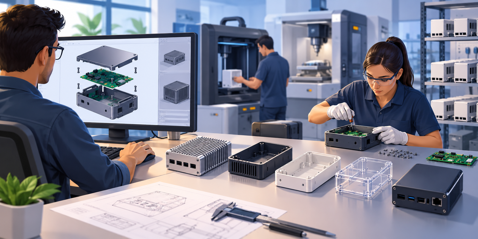
Why Electronics Enclosure Prototyping Matters
An electronics enclosure is the mechanical interface between the electronic assembly and its operating environment. It holds the PCB, connectors, displays, switches, cables, batteries and other components while protecting them from mechanical damage, contamination and environmental exposure.
During product development, the enclosure also has to work with the actual PCB rather than an idealised representation of it. Component heights, connector locations, mounting-hole tolerances, cable bend radii, heat-generating components and assembly access can all affect the final housing.
Prototyping allows these interfaces to be physically checked before production tooling, injection moulds or high-volume sheet-metal programs are released.
Typical applications include industrial controllers, IoT gateways, sensor products, robotics electronics, automotive modules, medical equipment, power electronics, communication equipment, laboratory instruments and consumer products.
What Is Electronics Enclosure Prototyping?
Electronics enclosure prototyping is the development and manufacture of a physical housing prototype used to evaluate the mechanical, electrical and environmental interfaces of an electronic product.
Depending on the development stage, the prototype may be manufactured using CNC machining, additive manufacturing, sheet-metal fabrication, vacuum casting, prototype tooling or another process that can reproduce the important characteristics of the intended product.
The objective is not necessarily to reproduce the final production process immediately. Instead, the prototype should answer the engineering questions that matter at that stage: Does the PCB fit? Are connectors accessible? Can the product be assembled? Is there enough clearance? Can heat escape? Does the enclosure have sufficient strength? Can the intended production process manufacture the geometry?
What Should an Enclosure Prototype Validate?
Mechanical Fit
Confirm PCB mounting, enclosure dimensions, internal clearances, component heights and mechanical interfaces.
Assembly
Check whether PCBs, cables, connectors, fasteners and other components can be installed in the intended sequence.
User Interface
Validate access to displays, buttons, switches, ports, indicators and other external interfaces.
Thermal Behaviour
Establish whether heat-generating components have suitable conduction, ventilation or heatsink interfaces.
Environmental Protection
Validate sealing concepts, gaskets, cable entry points, protective covers and other environmental interfaces.
Manufacturability
Identify geometry, tolerance and assembly issues before production tooling or recurring manufacturing is released.
How Electronics Enclosure Prototyping Works
A robust prototype programme begins with the product interfaces rather than simply converting an outer CAD surface into a physical model.
Common Electronics Enclosure Prototype Materials
Material selection depends on the enclosure’s structural, thermal, electrical, environmental and appearance requirements. Prototype material does not always need to be identical to the final production material, but differences must be understood.
| Material | Typical Prototype Process | Advantages | Considerations |
|---|---|---|---|
| Aluminium | CNC machining | Strong, lightweight, good thermal conductivity | Higher machining cost; tooling marks and surface finish must be considered |
| ABS / PC-ABS | 3D printing, vacuum casting, injection molding | Good for product housings and consumer-style applications | Prototype process can change surface and mechanical behaviour |
| Polycarbonate | CNC machining, additive manufacturing | Good impact resistance and transparency options | Material/process combination should match the intended application |
| Nylon | CNC machining, SLS and other additive processes | Useful for functional prototypes and complex geometry | Moisture absorption and anisotropy can affect dimensions and properties |
| Sheet steel | Laser cutting + bending | Robust industrial enclosure construction | Bend allowances, bend radii and hardware installation must be considered |
| Stainless steel | Laser cutting + bending / CNC | Corrosion resistance and industrial durability | Higher fabrication and finishing cost |
Electronics Enclosure Prototype Manufacturing Processes
CNC Machining
CNC machining is useful when the prototype requires accurate mounting interfaces, machined threads, precise connector openings or a metal enclosure that closely represents the final product.
Aluminium and engineering plastics are common choices. Critical features should be dimensioned and toleranced rather than relying on general CAD dimensions.
3D Printing
Additive manufacturing is useful for early design iterations, ergonomic studies, interference checks and complex geometries.
Engineers should account for build orientation, layer behaviour, dimensional capability, surface finish and material properties when using printed parts for functional testing.
Sheet Metal Fabrication
Sheet metal is particularly useful for industrial electronics, control equipment and rugged housings. Prototype production can involve laser cutting, bending, welding, hardware insertion and powder coating.
Bend radius, K-factor, bend sequence, hole-to-edge distance and assembly hardware should be considered during design.
Vacuum Casting
Vacuum casting can produce multiple polyurethane parts from a master pattern when appearance and material characteristics need to be closer to moulded parts than a basic printed prototype.
It can be useful for pilot quantities and appearance validation before production tooling.
Prototype Injection Molding
When the final enclosure will be injection molded, prototype or bridge tooling can provide a more representative evaluation of the production material, geometry and molding behaviour.
Tooling investment should be justified against expected prototype and pilot quantities.
Hybrid Prototypes
Not every prototype needs one manufacturing process. Engineers may combine a machined metal base, printed cover, purchased fasteners and production PCB to create a functional engineering prototype quickly.
PCB and Enclosure Integration
The enclosure cannot be designed independently from the PCB. The PCB layout defines connector positions, component clearances, mounting points and the maximum component envelope inside the housing.
A prototype should therefore be evaluated using the actual PCB or an accurate mechanical representation of the board.
- PCB length, width and thickness
- Mounting-hole locations and diameters
- PCB-to-wall clearance
- Maximum component height
- Connector location and mating clearance
- Display and switch alignment
- Heat-generating components
- Heatsink or thermal interface requirements
- Cable bend radius
- Service and replacement access
- Grounding and shielding interfaces
- Fastener and standoff access
Where the product uses SMT and high-density PCB assembly, component height variation and connector position should be included in the enclosure clearance analysis. For PCB manufacturing and assembly context, see Manufyn’s Electronic Assembly resources.
Electronics Enclosure Design Considerations
Wall Thickness
Wall thickness must suit the selected material and manufacturing process. Thin sections can cause weakness, distortion or molding difficulties.
Mounting Bosses
Boss geometry should provide sufficient strength without interfering with PCB components or creating excessive stress concentrations.
Clearances
Provide appropriate clearance around PCBs, connectors, cables, fasteners and moving or removable components.
Fasteners
Select screws, inserts, captive hardware or clips based on assembly requirements, serviceability and production volume.
Connector Access
Connector openings must account for mating plugs, latching mechanisms, cable bend radius and operator access.
Serviceability
Consider how technicians will open the housing, replace the PCB, access connectors or perform field service.
Design for Manufacturing and Assembly
A prototype is an opportunity to identify DFM and DFA problems before production tooling and recurring manufacturing begin. The review should consider the actual process that will be used for production rather than simply asking whether the prototype can be manufactured.
DFM Questions
- Can the selected manufacturing process achieve the required geometry?
- Are critical dimensions realistically toleranced?
- Are wall thicknesses suitable for the selected process?
- Are internal corners compatible with machining or tooling?
- Are sheet-metal bends and reliefs correctly designed?
- Can required surface finishes be produced consistently?
- Are materials commercially available?
- Can the geometry be inspected economically?
DFA Questions
- Can the PCB be installed without excessive handling?
- Can connectors be installed and accessed easily?
- Is the assembly sequence logical?
- Are fasteners accessible to assembly tools?
- Can cables be routed without excessive bending?
- Can the enclosure be opened for service?
- Can final functional testing be performed efficiently?
Thermal Management in Electronics Enclosures
Enclosure design can significantly influence electronics temperature. Heat generated by processors, power electronics, voltage regulators, LEDs, motors or other components must ultimately be transferred away from the heat source.
Depending on the application, the enclosure may use conduction to a metal housing, heatsinks, thermal interface materials, ventilation openings or forced airflow.
A prototype should therefore verify critical thermal interfaces rather than treating the enclosure purely as a cosmetic housing.
Prototype thermal check
Measure temperatures under representative operating conditions and document ambient temperature, operating load, measurement locations and test duration. Prototype results should not automatically be treated as production qualification data when materials or manufacturing processes will change.
EMI, EMC and Shielding Considerations
Electronics enclosures can form part of the electromagnetic control strategy of a product. Metal housings may provide shielding when properly designed and electrically bonded, while plastic housings may require conductive coatings, shielding components or other design measures.
Openings, seams, cable entry points and connector interfaces can influence electromagnetic performance. The final compliance strategy should be established with the relevant product standards and test requirements.
- Shielding material and coating requirements
- Electrical bonding between enclosure components
- Connector shielding
- Cable entry points
- Ventilation opening geometry
- Seam design
- Grounding requirements
- EMC test configuration
Sealing, IP Protection and Environmental Requirements
Electronics used outdoors, in industrial environments, vehicles or other demanding conditions may require protection against water, dust, chemicals, vibration or temperature variation.
Prototype enclosures should validate the sealing concept early where environmental protection is a design requirement.
- Gasket geometry
- Compression and sealing surfaces
- Fastener spacing
- Cable glands
- Connector sealing
- Vent membranes
- Drainage paths
- Housing joint design
- Material compatibility
If an IP rating or other environmental qualification is required, the production design should be tested using the applicable test method rather than assuming that a visually sealed prototype automatically meets the intended rating.
Surface Finishing for Electronics Enclosure Prototypes
Anodising
Common for aluminium housings where appearance, surface protection and a controlled finish are required.
Powder Coating
Frequently used on fabricated steel and aluminium enclosures for industrial products.
Painting
Useful when colour, appearance or a particular surface finish is required for prototype evaluation.
Bead Blasting
Can provide a uniform matte surface on suitable metal components before additional finishing.
Machined Finish
Suitable when prototype cost and functional validation are more important than final cosmetic appearance.
Texture Matching
For appearance-critical products, prototype surface texture should be selected with the intended production process in mind.
Inspection and Quality Control
Enclosure prototype inspection should be based on functional requirements and critical interfaces rather than measuring every CAD dimension with equal priority.
Typical Inspection Methods
- Digital caliper inspection
- Micrometer measurement
- Height gauge inspection
- CMM inspection for critical geometry
- Thread and hole verification
- Surface finish inspection
- Material verification
- Visual inspection
- PCB fit and clearance verification
- Connector mating verification
- Assembly and functional checks
Critical dimensions should be identified on the drawing with appropriate tolerances. Suppliers should not be expected to determine which dimensions are functionally critical from a 3D model alone.
Procurement Considerations for Electronics Enclosures
Buying an enclosure prototype is different from buying a catalogue plastic box. The supplier must understand the mechanical drawing, material, manufacturing process, finish, quantity and intended validation purpose.
Procurement teams should define what is fixed and what can be proposed by the supplier. For example, the material and critical interface dimensions may be fixed while the supplier can recommend a manufacturing process or non-critical tolerance.
| Procurement Factor | What to Evaluate |
|---|---|
| MOQ | Prototype minimum quantity and whether one-off production is supported |
| Lead Time | Engineering review, material procurement, machining/fabrication, finishing and inspection |
| Material | Material grade, availability, certification and substitution controls |
| Process | CNC, additive manufacturing, sheet metal, casting or tooling capability |
| Tolerances | Supplier’s demonstrated capability for critical dimensions |
| Finishing | Anodising, powder coating, painting, blasting or other specified finishes |
| Quality | Inspection equipment, inspection reports and quality system |
| Traceability | Material, batch, inspection and production records where required |
| Cost | Part price, setup, programming, tooling, finishing, inspection and packaging |
| Scalability | Ability to move from prototype to pilot and recurring production |
Electronics Enclosure Supplier Qualification Checklist
Technical Capability
- Can manufacture the required material?
- Has experience with the required process?
- Can achieve the specified tolerances?
- Has appropriate inspection equipment?
- Can manufacture required threads and inserts?
- Can manage surface finishing?
- Can support prototype quantities?
Quality System
- Documented quality procedures
- Incoming material control
- In-process inspection
- Final inspection
- Non-conformance handling
- Calibration system
- Traceability where required
Commercial Capability
- Transparent quotation
- Clear tooling and setup charges
- Defined lead time
- Capacity visibility
- Payment terms
- Packaging capability
- Export experience where required
Engineering Support
- Can review 2D drawings?
- Can review 3D CAD?
- Can identify DFM issues?
- Can propose practical manufacturing changes?
- Can support design iterations?
- Can transition to production?
Common Electronics Enclosure Prototype Problems
| Problem | Possible Cause | Detection Method | Corrective Action |
|---|---|---|---|
| PCB does not fit | Incorrect mounting-hole location, tolerance stack-up or enclosure dimension | Physical fit check and dimensional inspection | Review PCB datum scheme and enclosure tolerances |
| Connector cannot be accessed | Opening misalignment or insufficient clearance | Connector mating test | Update connector cutout and access geometry |
| PCB contacts enclosure | Insufficient component clearance or incorrect standoff height | Visual inspection and clearance measurement | Increase clearance or modify mounting geometry |
| Cover does not close | Interference between components, cables or enclosure features | Assembly test | Perform interference review and update assembly sequence |
| Thread damage | Incorrect thread specification, material or repeated assembly | Thread gauge / fastener test | Review thread design or use inserts where appropriate |
| Warped plastic housing | Material behaviour, additive process or molding conditions | Dimensional inspection | Review process, material and geometry |
| Overheating | Insufficient heat transfer or airflow | Thermal testing | Improve heatsink, conduction, ventilation or enclosure design |
| Surface finish mismatch | Prototype process differs from intended production process | Visual comparison | Define production finish and prototype representation clearly |
| Cable cannot be routed | Insufficient internal space or bend radius | Physical assembly check | Increase routing space or redesign cable path |
What Drives Electronics Enclosure Prototype Cost?
Material
Material grade, size, availability and minimum purchase quantity influence prototype cost.
Machine Time
CNC machining cost increases with material removal, complexity, setups and tight tolerances.
Programming
Complex CNC geometry can require significant CAM programming and process planning.
Tooling
Prototype tooling and injection moulds introduce upfront engineering and tooling costs.
Finishing
Anodising, painting, powder coating, texture and other finishes add processing cost and lead time.
Inspection
Tight tolerances and detailed inspection reports increase measurement and quality-control effort.
Prototype vs Low Volume vs Mass Production
| Factor | Prototype | Low Volume | Mass Production |
|---|---|---|---|
| Primary Objective | Validate design | Validate production and market demand | Repeatable production |
| Typical Process | CNC / 3D printing / sheet metal | Machining / bridge tooling / low-volume molding | Injection molding / production tooling / automated processes |
| Tooling Investment | Low | Moderate | Potentially significant |
| Unit Cost | High | Moderate | Lower at scale |
| Design Flexibility | High | Moderate | Lower after tooling release |
| Quality System | Prototype inspection | Defined inspection and process controls | Formal production quality controls |
The best prototype process is therefore determined by what needs to be learned. A 3D printed enclosure may be ideal for early clearance checks, while a CNC aluminium enclosure may be more appropriate for thermal or structural testing.
Procuring Electronics Enclosure Prototypes from India
India can support enclosure prototyping through a combination of CNC machining, sheet-metal fabrication, additive manufacturing, plastics processing, finishing and electronics assembly suppliers. The practical challenge for an overseas buyer is often not finding a manufacturer, but selecting the supplier whose process, quality system and communication discipline match the project.
Supplier Selection
Evaluate the supplier against the actual enclosure process. A company that can machine simple aluminium parts may not necessarily have the tooling, inspection or finishing capability required for a complex electronic housing.
Quality Audits
For recurring projects, review quality procedures, inspection equipment, calibration, material controls, non-conformance handling and production records.
Communication
Establish one controlled technical package containing the latest drawing revision, CAD files, BOM references, material requirements and inspection requirements.
Documentation
Prototype projects should maintain drawing revisions, inspection reports, material information, approved changes and supplier quotations. This becomes particularly important when the project moves from prototype to recurring production.
Packaging and Logistics
Prototypes can be susceptible to cosmetic damage during international transport. Packaging should protect finished surfaces, mounting features and fragile enclosure components.
Supplier Development
If the first prototype supplier is not intended to remain the production supplier, capture the manufacturing knowledge, inspection requirements and lessons learned before transferring the project.
Practical Buyer Checklist Before Issuing an RFQ
Technical Package
- 3D CAD model
- 2D manufacturing drawing
- Material specification
- Critical dimensions identified
- Surface finish specification
- Thread and insert requirements
- PCB dimensions
- Connector locations
- Required prototype quantity
Commercial Package
- Target quantity
- Required delivery date
- Shipping destination
- Packaging requirements
- Inspection report requirement
- Material certification requirement
- Expected production volume
- Future production intent
- Required Incoterm
Electronics Enclosure Prototyping FAQs
What is electronics enclosure prototyping?
It is the manufacture of a physical housing prototype used to validate PCB fit, mechanical interfaces, assembly, thermal behaviour, appearance and other product requirements before production.
What is the best process for an electronics enclosure prototype?
It depends on the validation objective. CNC machining is useful for precise functional prototypes, 3D printing is useful for rapid design iterations, sheet metal suits fabricated industrial housings, and prototype tooling can be appropriate when injection-molded production parts need to be evaluated.
Can I prototype an aluminium electronics enclosure?
Yes. CNC machining is commonly used for aluminium prototypes where strength, thermal behaviour, precise interfaces or a representative metal housing are required.
Can the PCB be included during enclosure prototyping?
Yes. Using the actual PCB or an accurate mechanical representation is strongly recommended when validating mounting, component clearance, connectors and cable routing.
Should the prototype use the same material as production?
Not always. Early prototypes can use representative materials, but material differences should be considered when validating thermal, structural, chemical, electrical or environmental performance.
Can enclosure prototypes include threaded inserts?
Yes. Press-fit, heat-set, threaded or other inserts can be incorporated depending on the material and manufacturing process.
How do I select an electronics enclosure supplier?
Evaluate manufacturing process capability, materials, tolerances, inspection equipment, finishing capability, engineering support, quality systems, lead time, communication and ability to transition to production.
Is 3D printing suitable for functional enclosure testing?
It can be suitable for many fit, clearance, ergonomic and assembly evaluations. However, printed materials and processes can behave differently from injection-molded or machined production materials.
How much does an electronics enclosure prototype cost?
Cost depends on material, dimensions, geometry, quantity, tolerances, machining time, finishing, tooling, inspection and shipping. A simple printed enclosure and a precision-machined aluminium housing can have very different cost structures.
Can an enclosure prototype be manufactured in India?
Yes. Prototype manufacturing in India can involve CNC machining, additive manufacturing, sheet-metal fabrication, plastics processing, finishing and prototype tooling. Supplier capability should be evaluated against the actual engineering requirements.
When should enclosure DFM be performed?
DFM should be considered before manufacturing begins and revisited when the production process changes. Early DFM reduces the likelihood of discovering manufacturability problems after tooling or production commitments.
Related Electronics & Manufacturing Resources
PCB Assembly & Final Enclosure Manufacturing
Understand how PCB assembly, enclosure manufacturing, wiring and final product integration fit together.
Explore PCB & Enclosure Manufacturing →Rapid Prototyping
Explore CNC machining, 3D printing, sheet metal, prototype tooling and the transition from prototype to production.
Explore Rapid Prototyping →Electronic Assembly
Learn about PCB assembly, SMT, through-hole assembly, soldering and functional testing.
Explore Electronic Assembly →Surface Mount Technology
Understand how SMT assembly influences PCB geometry, component placement and enclosure clearances.
Explore SMT →Manufacturing Resources
Browse Manufyn’s broader engineering, electronics and manufacturing knowledge resources.
Explore Knowledge Resources →Robotics Manufacturing
Explore enclosure, electronics, wiring and mechanical integration considerations for robotic products.
Explore Robotics Manufacturing →Electronics Procurement Support from India
Manufyn India Private Limited can support global product companies that need to identify, evaluate and coordinate electronics manufacturing suppliers in India.
For enclosure and electronics programmes, the requirement may involve multiple manufacturing processes rather than a single supplier. An enclosure may require CNC machining or sheet metal fabrication, while the complete product may also require PCB assembly, cable integration, testing and final assembly.
Manufyn can support the procurement programme through:
- India supplier identification
- Supplier capability assessment
- Supplier qualification
- RFQ management
- Technical quotation comparison
- Commercial comparison
- Quality coordination
- Production follow-up
- Inspection coordination
- Supplier development
- Packaging and logistics coordination
This approach is particularly useful when an overseas engineering or procurement team needs local coordination across several manufacturing suppliers while retaining control over the technical specification.
Evaluating Electronics Enclosure Manufacturing in India?
Share your enclosure CAD files, drawings, material requirements, prototype quantity and target delivery date. Manufyn can help evaluate the appropriate Indian manufacturing route and coordinate qualified suppliers.
Discuss Your Requirement