
Hot Runner vs Cold Runner Systems in Injection Molding: Complete Engineering Guide
Choosing between a Hot Runner and Cold Runner system is one of the most important decisions in injection mold design. The runner system directly affects tooling cost, material waste, cycle time, product quality, maintenance requirements, and overall manufacturing efficiency. This comprehensive guide explains how both systems work, compares their advantages and disadvantages, highlights real-world applications, and helps engineers, buyers, and product developers select the most suitable runner system for their injection molding project.
Which Runner System Should You Choose?
| If You Need… | Recommended System |
|---|---|
| Prototype Tooling | Cold Runner |
| Production under 50,000 Parts | Cold Runner |
| Production above 150,000 Parts | Hot Runner |
| Minimal Material Waste | Hot Runner |
| Frequent Color Changes | Cold Runner |
| Premium Surface Finish | Valve Gate Hot Runner |
Hot Runner vs Cold Runner Systems
Injection molding is one of the most widely used manufacturing processes for producing high precision plastic components in industries such as automotive, medical devices, electronics, aerospace, industrial equipment, consumer products, and packaging. While the plastic part often receives the most attention, the performance of the mold itself plays a crucial role in determining manufacturing success. One of the most critical design decisions during Injection Molding tooling development is selecting the appropriate runner system.
The runner system is responsible for transporting molten plastic from the injection molding machine nozzle into each cavity of the mold. A poorly designed runner system can increase material waste, extend cycle times, create filling imbalances, introduce quality defects, and significantly increase production costs.
Modern mold designers generally choose between two primary runner technologies:
- Cold Runner Systems
- Hot Runner Systems
Each system offers distinct advantages depending on production volume, polymer type, tooling budget, maintenance strategy, and product complexity. Understanding these differences allows manufacturers to optimize quality, productivity, and long-term manufacturing costs.
Although Hot Runner molds typically require a higher initial investment, they often deliver significant long-term savings through reduced plastic waste, shorter cycle times, improved automation, and increased manufacturing efficiency, particularly in high-volume production environments.
Contents
- What is a Runner System?
- Components of a Runner System
- How Molten Plastic Flows Inside a Mold
- Cold Runner System
- Types of Cold Runner Systems
- Hot Runner System
- Open Gate Hot Runner
- Valve Gate Hot Runner
- Hot Runner vs Cold Runner Comparison
- Material Compatibility
- Cost Comparison
- Cycle Time Analysis
- Material Waste Comparison
- Design for Manufacturability (DFM)
- Mold Maintenance
- Common Design Mistakes
- Industry Applications
- Frequently Asked Questions
- Why Choose Manufyn
What is a Runner System in Injection Molding?
A runner system is the network of channels inside an injection mold that transports molten plastic from the injection molding machine nozzle to one or more mold cavities. Although it occupies only a small portion of the tooling, the runner system has a significant influence on cycle time, filling balance, pressure loss, material consumption, dimensional consistency, and overall manufacturing cost.
Whether you are manufacturing a few prototype components or millions of production parts, selecting the correct runner system is essential for achieving consistent quality and maximizing return on tooling investment. During every tooling project, Manufyn evaluates production volume, material selection, gate location, cooling strategy, and manufacturability before recommending either a Hot Runner or Cold Runner system.
Every injection molding project also begins with a comprehensive Design for Manufacturability (DFM) review. Early engineering decisions regarding wall thickness, gate placement, runner balancing, and cooling channel design can significantly reduce tooling modifications while improving mold performance throughout production.
Many manufacturers focus only on tooling price during supplier selection. However, runner design affects every molded part throughout the entire life of the mold. A well-designed runner system often reduces total manufacturing cost far more than the initial tooling investment.
Components of an Injection Molding Runner System
Regardless of whether a Hot Runner or Cold Runner system is used, every injection mold contains several critical flow elements that guide molten polymer from the machine barrel into the mold cavity.
| Component | Purpose |
|---|---|
| Sprue | Transfers molten plastic from the machine nozzle into the mold. |
| Primary Runner | Distributes plastic from the sprue toward secondary runners. |
| Secondary Runner | Balances flow between multiple cavities. |
| Gate | Controls how molten plastic enters the molded component. |
| Cavity | Forms the final geometry of the plastic part. |
| Cooling Channels | Remove heat and determine overall production cycle time. |
Each of these components influences pressure drop, filling pattern, weld line formation, shrinkage, and dimensional accuracy. In multi-cavity tooling, runner balancing becomes even more critical because each cavity must receive molten material simultaneously to maintain identical part quality.
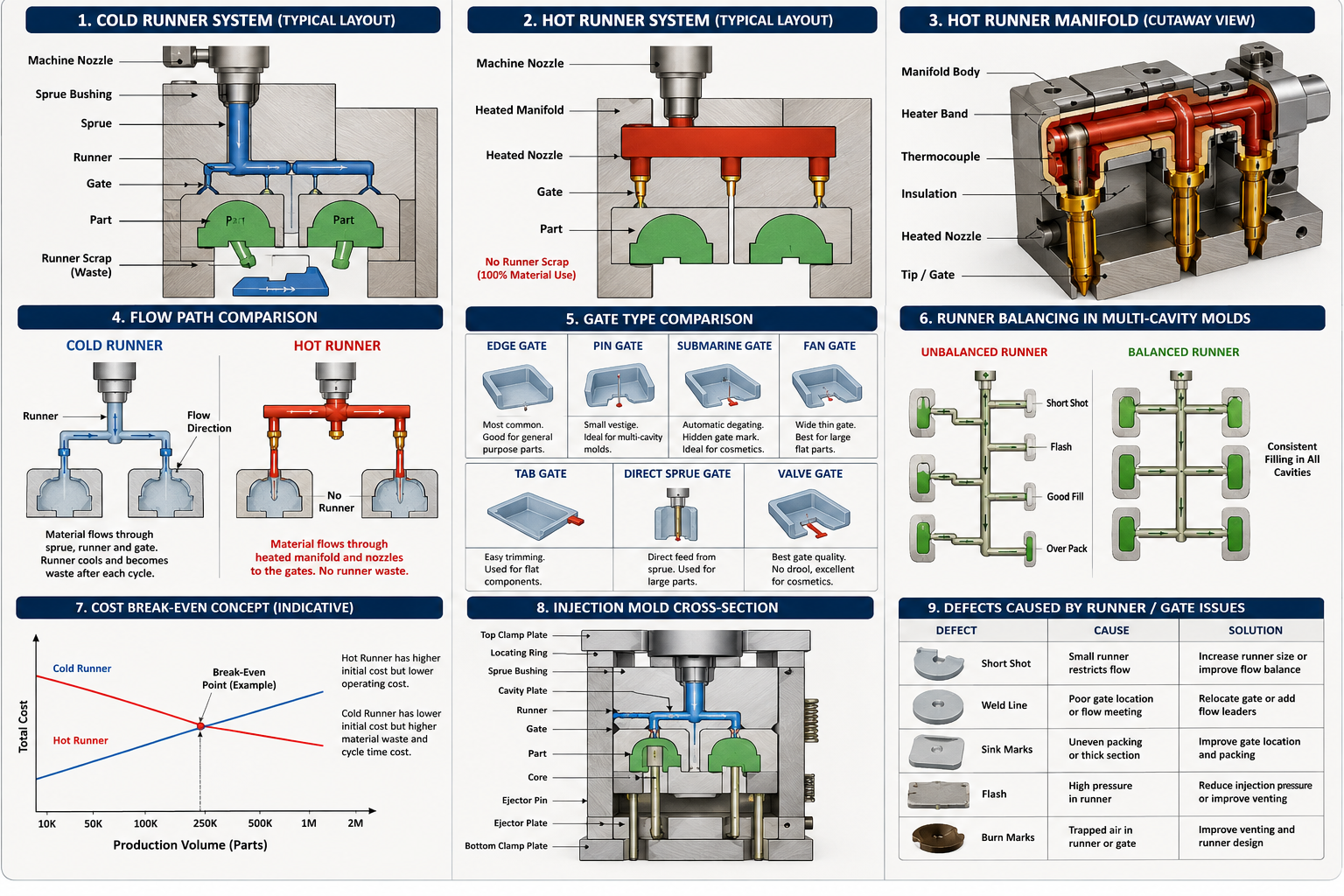
Figure 1 – Major components of a plastic injection mold runner system.
How Molten Plastic Flows Through an Injection Mold
Understanding the flow path helps explain why runner system selection has such a significant impact on product quality. During every molding cycle, plastic pellets are heated inside the injection molding machine until they reach a molten state. The reciprocating screw then injects the material under controlled pressure into the mold.
The molten polymer follows this sequence:
- Injection Machine Nozzle
- Sprue
- Primary Runner
- Secondary Runner
- Gate
- Mold Cavity
- Packing Phase
- Cooling Phase
- Part Ejection
Each stage must be carefully optimized to prevent defects such as short shots, sink marks, flash, burn marks, weld lines, voids, or excessive residual stresses. Runner diameter, gate geometry, mold temperature, injection pressure, and polymer viscosity all influence the final result.
Modern manufacturers increasingly rely on Mold Flow Analysis software during the DFM stage to predict flow behavior before any steel is cut. This minimizes expensive tooling modifications while shortening product development cycles.
Injection Molding Flow Process
Plastic Pellets
↓
Machine Barrel Heating
↓
Injection Screw
↓
Machine Nozzle
↓
Sprue
↓
Runner System
↓
Gate
↓
Mold Cavity
↓
Packing Pressure
↓
Cooling
↓
Part Ejection
Why Runner System Design Is Critical
Many manufacturers underestimate the importance of runner design until production begins. An inefficient runner system wastes raw material, increases cycle time, and creates inconsistent filling across multiple cavities. Even a small imbalance in flow can lead to dimensional variation, cosmetic defects, or premature tool wear.
A properly engineered runner system provides several advantages:
- Balanced cavity filling
- Reduced pressure loss
- Lower injection pressure requirements
- Improved dimensional consistency
- Reduced plastic scrap
- Shorter production cycles
- Higher automation capability
- Improved mold life
- Lower manufacturing cost per part
At Manufyn, runner system selection is evaluated alongside mold steel selection, cooling channel layout, gate design, and part geometry to deliver production-ready tooling. This integrated engineering approach is especially valuable when developing complex tooling featuring collapsible core mechanisms, split side core tooling, or prototype molds for new product development.
For customers validating new products before committing to hardened production tooling, prototype tooling combined with optimized runner design enables faster design iterations while reducing investment risk. Learn more through our guides on Rapid Prototype Casting & Moulding, Prototype Injection Moulding, and our case study on Rapid Prototyping for a Global Medical Startup.
Similarly, precision mold components such as cavities, cores, sliders, lifters, and inserts are manufactured using advanced CNC machining services, including 3-axis, 4-axis, 5-axis machining, EDM, and precision grinding. You can also explore our case study on 5-Axis Machining for Medical Device Prototyping to understand how precision machining supports high-performance tooling.
What is a Cold Runner System?
A Cold Runner System is the traditional method of delivering molten plastic from the injection molding machine to the mold cavity. Unlike a Hot Runner System, the runner channels are not heated. Instead, the runner cools together with the molded component during every production cycle.
Once the mold opens, both the finished component and the solidified runner are ejected simultaneously. Depending on the material and production requirements, the runner may either be recycled, reground, or discarded as manufacturing scrap.
Cold Runner tooling remains one of the most widely used solutions because of its simplicity, lower tooling investment, ease of maintenance, and flexibility across a wide range of thermoplastics. It is particularly suitable for prototype tooling, bridge tooling, low-volume production, and products that require frequent material or color changes.
For manufacturers developing new products, Cold Runner molds are often paired with Prototype Injection Moulding to validate product design before investing in fully optimized production tooling.
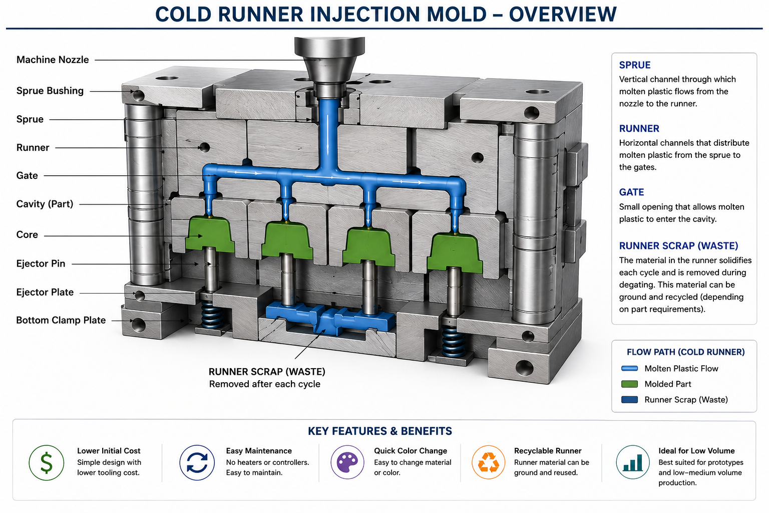
Figure 2: Typical Cold Runner System inside an Injection Mold.
How a Cold Runner System Works
Every injection molding cycle follows the same sequence.
- Plastic pellets are melted inside the injection molding machine.
- Molten plastic enters the mold through the sprue.
- The material flows through the primary and secondary runners.
- The gate directs plastic into each mold cavity.
- The cavity fills completely.
- Both the molded component and runner cool together.
- The mold opens.
- The runner and molded part are ejected together.
- The runner is separated from the molded component.
- The runner is either recycled or discarded.
Because the runner solidifies during every molding cycle, Cold Runner systems generally require slightly longer cooling times compared to Hot Runner systems. However, they remain an excellent choice for many manufacturing applications because of their lower tooling cost and simpler construction.
Advantages of Cold Runner Systems
| Benefit | Explanation |
|---|---|
| Lower Tool Cost | No heated manifold, heaters, thermocouples, or temperature controllers are required. |
| Simple Maintenance | Fewer components reduce maintenance complexity and repair costs. |
| Easy Color Change | Runner material is completely removed during every production cycle, making color transitions faster. |
| Material Flexibility | Suitable for most commodity and engineering thermoplastics. |
| Lower Initial Investment | Ideal for startups, product validation, and low-volume production. |
| Reliable Operation | Less dependence on electrical heating systems reduces operational complexity. |
Disadvantages of Cold Runner Systems
Although Cold Runner molds offer lower tooling costs, manufacturers should also consider the long-term operational costs associated with runner waste and longer cycle times.
- Higher material consumption due to runner scrap
- Longer cooling cycles
- Additional labor for runner separation
- Higher cost per part during high-volume production
- More post-processing for automated production lines
- Reduced sustainability because of plastic waste
For production programs involving millions of components annually, these recurring costs often outweigh the initial savings achieved through simpler tooling.
Types of Cold Runner Systems
1. Two Plate Mold
The Two Plate Mold is the simplest and most widely used Cold Runner design. The runner and molded part are ejected together when the mold opens. It offers excellent reliability, simple maintenance, and lower manufacturing costs, making it ideal for straightforward part geometries.
2. Three Plate Mold
A Three Plate Mold introduces an additional plate that automatically separates the runner from the molded component during mold opening. This configuration supports multiple gate locations and improves gate placement flexibility for complex components.
Three Plate tooling is commonly used for products requiring centrally located gates or multiple cavity layouts.
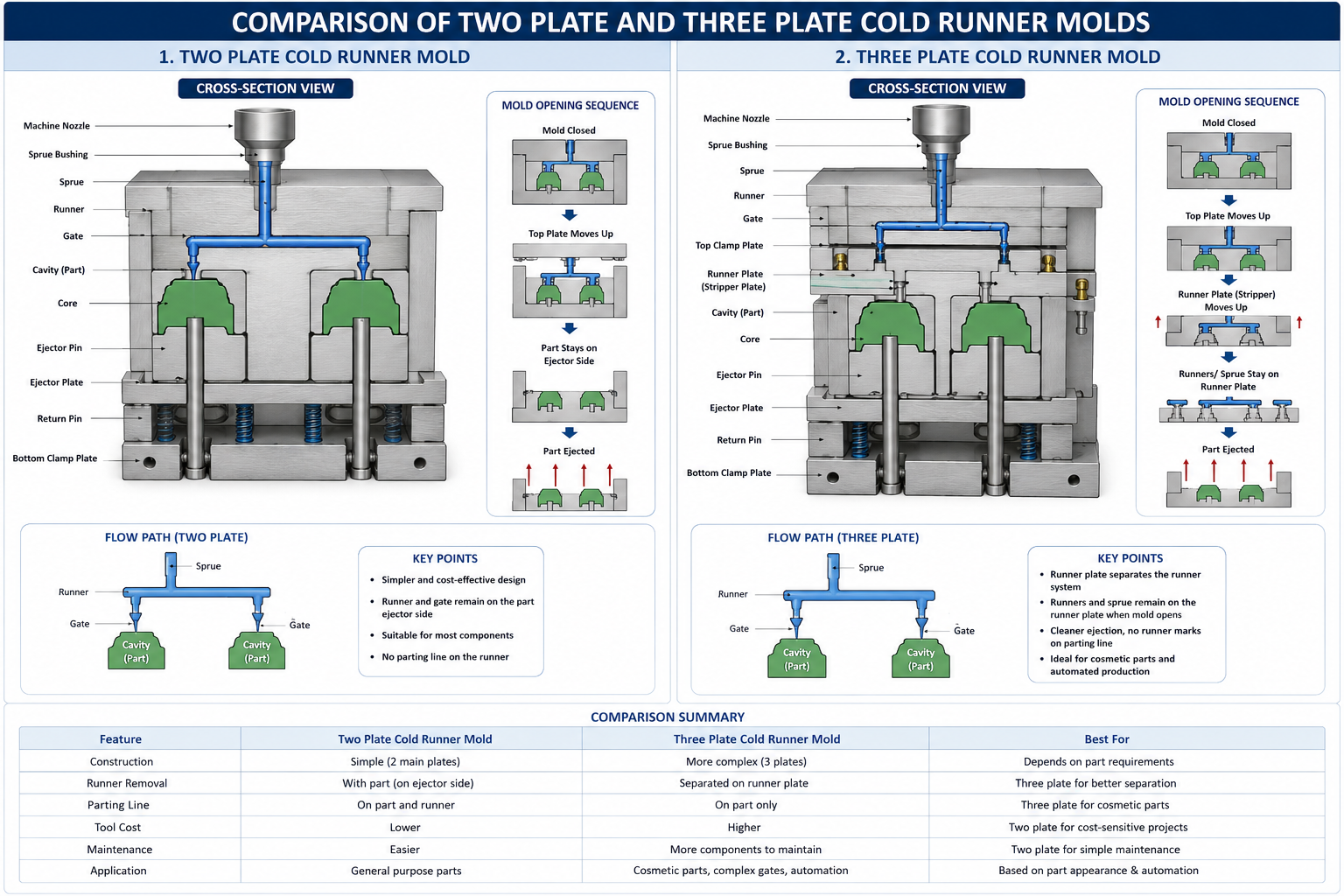
Figure 3: Comparison of Two Plate and Three Plate Cold Runner molds.
Materials Commonly Processed Using Cold Runner Systems
Cold Runner systems support virtually every major thermoplastic used in industrial manufacturing.
| Material | Typical Applications |
|---|---|
| ABS | Consumer products and electronics housings |
| Polypropylene (PP) | Packaging and automotive interiors |
| Polyethylene (HDPE) | Industrial containers and caps |
| Nylon (PA6 / PA66) | Mechanical and automotive components |
| POM (Acetal) | Precision gears and mechanical parts |
| PC | Transparent engineering products |
| TPU | Flexible industrial components |
| PEEK | Medical and aerospace applications |
Material selection should always be reviewed alongside runner design, gate size, cooling layout, and expected production volume. At Manufyn, these engineering parameters are evaluated during tooling development to improve manufacturability and minimize production risk.
When Should You Choose a Cold Runner System?
A Cold Runner system is typically the preferred solution when tooling investment needs to be minimized or production volumes do not justify the additional cost of a Hot Runner manifold.
- Prototype tooling
- Bridge tooling
- Low-volume production
- Frequent material changes
- Frequent color changes
- Simple part geometries
- Cost-sensitive projects
- Product development and validation
Many customers also choose Cold Runner molds during early product development before transitioning to a Hot Runner system once production volumes increase. This phased approach reduces development costs while maintaining design flexibility.
Related Resources from Manufyn
What is a Hot Runner System?
A Hot Runner System is an advanced injection molding technology that keeps the molten plastic inside the runner channels at processing temperature throughout the entire molding cycle. Unlike a Cold Runner System, the runner never solidifies, allowing molten polymer to flow directly into the mold cavity without generating runner scrap.
The system consists of a heated manifold, heated nozzles, electrical heaters, thermocouples, and a temperature controller that work together to maintain a consistent melt temperature. Because the runner remains molten, only the finished plastic component is ejected from the mold after each cycle.
Today, Hot Runner systems are widely used in the automotive, medical device, electronics, consumer goods, packaging, electrical, and aerospace industries where manufacturers require shorter cycle times, lower material waste, excellent dimensional consistency, and high-volume production efficiency.
When developing high-performance tooling, Manufyn combines optimized Hot Runner technology with precision CNC Machining, Injection Molding, and Design for Manufacturability (DFM) reviews to maximize tooling performance throughout the production lifecycle.
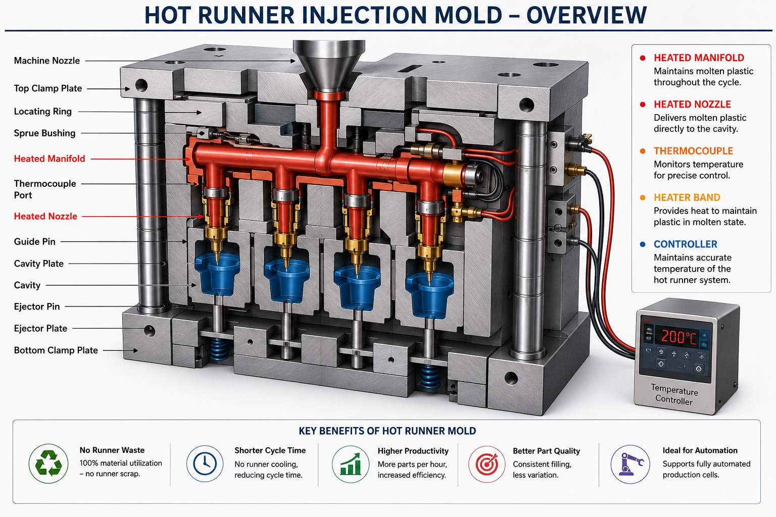
Figure 4 – Typical Hot Runner System inside an Injection Mold.
How a Hot Runner System Works
Although the injection molding process is similar to a Cold Runner mold, the major difference is that the runner channels are continuously heated. Instead of cooling together with the molded component, the molten plastic remains inside the manifold until the next injection cycle.
- Plastic pellets are melted inside the injection molding machine.
- The reciprocating screw injects molten polymer into the heated manifold.
- The heated manifold distributes molten plastic evenly to every cavity.
- Heated nozzles maintain melt temperature until the material reaches the gate.
- The cavity fills under controlled pressure.
- The molded component cools while the runner remains molten.
- The mold opens.
- Only the finished component is ejected.
- The remaining molten plastic is immediately available for the next injection cycle.
Since there is no solidified runner to cool and eject, production cycles become significantly shorter while material utilization improves dramatically.
Major Components of a Hot Runner System
| Component | Function |
|---|---|
| Heated Manifold | Distributes molten plastic uniformly from the sprue to each nozzle. |
| Hot Runner Nozzle | Maintains melt temperature and delivers polymer into the gate. |
| Cartridge Heaters | Provide consistent heating throughout the manifold and nozzles. |
| Thermocouples | Continuously monitor operating temperature. |
| Temperature Controller | Maintains precise processing temperature for stable molding conditions. |
| Gate Insert | Controls polymer entry into the mold cavity. |
Each component must be engineered with precision because temperature variations of only a few degrees can influence polymer viscosity, flow behavior, weld line formation, shrinkage, and cosmetic surface quality.
Open Gate Hot Runner System
An Open Gate Hot Runner System allows molten plastic to flow continuously through the nozzle without any mechanical shut-off mechanism. The gate freezes naturally after the packing phase, making this the simplest and most economical Hot Runner configuration.
Advantages
- Lower tooling cost than Valve Gate systems
- Simpler construction
- Fewer moving components
- Reduced maintenance requirements
- Reliable for many engineering thermoplastics
Limitations
- Gate vestige may remain visible
- Less precise gate control
- Not ideal for cosmetic Class-A surfaces
- Limited sequential filling capability
Valve Gate Hot Runner System
A Valve Gate Hot Runner System incorporates a precision valve pin that mechanically opens and closes each gate during the injection cycle. This allows manufacturers to precisely control melt flow, gate timing, cavity balancing, and sequential filling.
Valve Gate technology is widely used for premium automotive, medical, consumer electronics, and packaging applications where cosmetic quality and dimensional consistency are critical.
Advantages
- No gate vestige
- Superior cosmetic finish
- Sequential cavity filling
- Excellent dimensional repeatability
- Reduced weld lines
- Lower internal stresses
- Ideal for multi-cavity tooling
Typical Applications
- Automotive bumpers
- Medical components
- Consumer electronics
- Electrical housings
- High-volume packaging
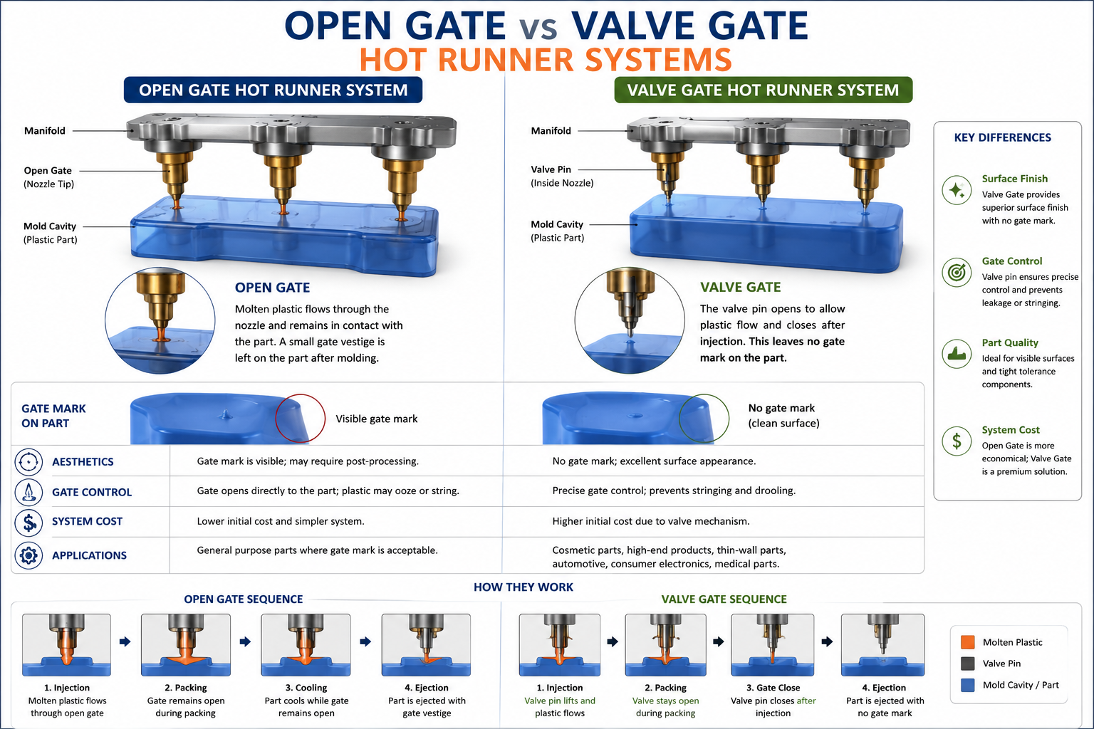
Figure 5 – Open Gate vs Valve Gate Hot Runner Systems.
Advantages of Hot Runner Systems
| Benefit | Manufacturing Impact |
|---|---|
| No Runner Scrap | Nearly 100% material utilization. |
| Shorter Cycle Time | Higher machine productivity. |
| Lower Cost Per Part | Excellent return on investment for high-volume production. |
| Balanced Filling | Improved dimensional consistency. |
| Higher Automation | No manual runner separation required. |
| Lower Injection Pressure | Reduced stress on tooling and molding machine. |
| Better Surface Finish | Improved cosmetic quality. |
| Reduced Environmental Waste | Supports sustainable manufacturing practices. |
Challenges of Hot Runner Systems
Although Hot Runner molds offer significant long-term manufacturing advantages, they also require greater engineering expertise during mold design, manufacturing, maintenance, and process optimization.
- Higher initial tooling investment
- More complex mold construction
- Temperature controller required
- Higher maintenance costs
- Longer repair time if components fail
- More difficult material and color changes
- Requires experienced process engineers
For this reason, manufacturers generally justify Hot Runner systems when annual production volumes are high enough to recover the additional tooling investment through reduced material waste and improved production efficiency.
Typical Applications of Hot Runner Systems
Hot Runner molds are commonly selected for products that demand high production efficiency, excellent cosmetic quality, and minimal material waste.
- Automotive interior components
- Automotive lighting components
- Medical device housings
- Medical disposable products
- Consumer electronics
- Electrical connectors
- Bottle caps and closures
- Food packaging
- Industrial engineering plastics
- Multi-cavity precision components
Many of these products also require complex tooling solutions such as collapsible cores, split side cores, precision sliders, lifters, and hardened mold inserts. Explore Manufyn’s case studies on Collapsible Core Injection Moulding, Split Side Core Tooling, and Injection Mold Tooling Transfer to see how optimized tooling design improves manufacturing performance.
Manufyn Engineering Recommendation
If your project involves annual production volumes above approximately 100,000 to 150,000 parts, engineering-grade thermoplastics, or automated production lines, investing in a Hot Runner System often provides a lower total cost of ownership despite its higher initial tooling cost. Factors such as resin price, cycle time reduction, scrap elimination, and labor savings should all be evaluated when selecting the most suitable runner system.
Hot Runner vs Cold Runner Systems: Complete Comparison
Choosing between a Hot Runner and a Cold Runner system depends on far more than tooling cost alone. Production volume, resin price, cycle time, part complexity, cosmetic requirements, automation level, maintenance capability, and long-term operating costs all influence the most economical solution.
While Cold Runner molds continue to be widely used for prototype tooling and lower production quantities, Hot Runner technology has become the preferred solution for high-volume manufacturing where material savings and productivity outweigh the higher initial tooling investment.
If your project is still in the design stage, Manufyn recommends conducting a comprehensive Design for Manufacturability (DFM) review before finalizing the tooling concept. Our Injection Molding Services team evaluates gate location, runner balancing, cooling efficiency, mold complexity, expected production volume, and resin selection to recommend the most suitable runner system.
Hot Runner vs Cold Runner Comparison Table
| Parameter | Hot Runner | Cold Runner |
|---|---|---|
| Initial Tool Cost | High | Low |
| Production Cost Per Part | Lower for high volumes | Higher due to runner waste |
| Material Waste | Very Low | High |
| Runner Scrap | None | Generated every cycle |
| Cycle Time | Shorter | Longer |
| Cooling Time | Reduced | Longer |
| Automation | Excellent | Good |
| Maintenance | More Complex | Simple |
| Tool Complexity | High | Low |
| Color Change | More Difficult | Easier |
| Material Change | Requires Purging | Simpler |
| Surface Finish | Excellent | Very Good |
| Gate Vestige | Minimal (Valve Gate) | Visible |
| Best Production Volume | Medium to High | Prototype to Medium |
| Environmental Impact | Low Waste | Higher Plastic Waste |
1. Tooling Cost Comparison
One of the first considerations during any tooling project is the initial mold investment. A Cold Runner mold is generally less expensive because it does not require heated manifolds, cartridge heaters, thermocouples, wiring, or temperature controllers.
Hot Runner molds include additional precision-engineered components and electrical systems, increasing tooling cost. However, this higher investment is often recovered through lower operating costs, particularly in high-volume manufacturing.
| Cost Element | Hot Runner | Cold Runner |
|---|---|---|
| Mold Base | Higher | Lower |
| Manifold | Required | Not Required |
| Temperature Controller | Required | Not Required |
| Electrical Components | Yes | No |
2. Material Waste Comparison
Material utilization is one of the biggest advantages of Hot Runner technology. Because the runner remains molten throughout production, almost all injected material becomes part of the finished product.
Cold Runner molds generate a solidified runner after every cycle. Although some thermoplastics can be reground and reused, engineering materials such as PEEK, medical-grade polymers, or glass-filled resins often have strict limitations on regrind usage.
Annual Production: 500,000 Parts
Average Runner Weight: 15 grams
Total Runner Scrap Generated: 7,500 kg every year
3. Cycle Time Comparison
Cycle time has a direct impact on manufacturing productivity and machine utilization.
Since Cold Runner molds require both the molded component and the runner to cool before ejection, cooling time increases. Hot Runner molds eliminate runner cooling entirely, allowing the mold to open sooner and improving machine output.
| Factor | Hot Runner | Cold Runner |
|---|---|---|
| Runner Cooling | No | Yes |
| Machine Productivity | Higher | Lower |
| Production Output | Higher | Lower |
4. Part Quality Comparison
Hot Runner systems maintain a consistent melt temperature throughout the injection cycle, reducing pressure loss and improving cavity balance. This generally results in better dimensional consistency, lower internal stress, and improved cosmetic appearance.
Cold Runner molds can also produce high-quality parts, but they rely more heavily on optimized runner geometry, balanced gate locations, and careful process control.
- Better cavity balance
- Reduced weld lines
- Improved dimensional accuracy
- Lower residual stress
- Improved cosmetic finish
- Better repeatability
5. Maintenance Comparison
Cold Runner molds are mechanically simpler and therefore easier to maintain. Repairs typically involve gates, runners, ejectors, sliders, lifters, or mold inserts.
Hot Runner systems introduce additional components including heaters, thermocouples, manifolds, valve pins, wiring, and controllers. Preventive maintenance becomes essential to maintain stable production.
6. Sustainability Comparison
Manufacturers are increasingly evaluating sustainability alongside cost and productivity.
Hot Runner technology reduces virgin resin consumption by eliminating runner scrap, lowering disposal requirements and improving overall material efficiency.
This is especially valuable when processing high-cost engineering plastics including PEEK, Ultem, PPS, PA66 GF30, and other specialty polymers.
When Should You Choose Each Runner System?
| Production Scenario | Recommended System |
|---|---|
| Prototype Development | Cold Runner |
| Bridge Tooling | Cold Runner |
| Low Volume Production | Cold Runner |
| High Volume Production | Hot Runner |
| Medical Devices | Hot Runner |
| Automotive Components | Hot Runner |
| Packaging | Hot Runner |
| Frequent Color Changes | Cold Runner |
| Premium Cosmetic Parts | Valve Gate Hot Runner |
| Engineering Plastics | Depends on production volume |
Expert Recommendation from Manufyn
Selecting the right runner system should never be based solely on tooling cost. The total cost of ownership includes resin consumption, machine utilization, labor, maintenance, scrap generation, production volume, and expected mold life. By evaluating these factors during the design stage, manufacturers can significantly reduce long-term production costs while improving part quality and manufacturing efficiency.
For projects involving complex tooling, advanced cooling strategies, or precision mold components, explore our CNC Machining Services, Injection Molding Solutions, and case studies including Injection Mold Tooling Transfer, Collapsible Core Tooling, Split Side Core Design, VMC vs HMC CNC Machining, and Vertical Turning Lathe (VTL) Machining to see how precision manufacturing supports high-performance injection molds.
Design for Manufacturability (DFM): Selecting the Right Runner System
Choosing between a Hot Runner and Cold Runner system should begin long before the mold is manufactured. During the Design for Manufacturability (DFM) stage, engineers evaluate the product geometry, material characteristics, production volume, quality expectations, and tooling budget to determine the most suitable runner configuration.
At Manufyn, every Injection Molding project begins with a comprehensive engineering review to minimize tooling modifications, improve mold life, reduce production costs, and optimize part quality.
An effective DFM study examines not only the plastic component but also the complete manufacturing process, including gate design, runner balancing, cooling channels, venting, shrinkage compensation, ejection methods, and precision machining of mold components.
Key Factors Considered During Runner System Selection
| Engineering Factor | Why It Matters |
|---|---|
| Annual Production Volume | Determines whether Hot Runner investment provides ROI. |
| Material Cost | Expensive engineering plastics benefit from reduced runner scrap. |
| Part Geometry | Complex parts require balanced filling. |
| Wall Thickness | Influences gate location and flow resistance. |
| Surface Finish | Valve Gate systems improve cosmetic appearance. |
| Tolerance Requirements | Precision parts require consistent filling. |
| Automation Level | High automation favors Hot Runner systems. |
| Expected Mold Life | Long production programs justify higher tooling investment. |
Runner Balancing in Multi Cavity Injection Molds
Runner balancing ensures that molten plastic reaches every cavity at the same time and under nearly identical pressure. An unbalanced runner system causes dimensional variation, inconsistent filling, flash, sink marks, and increased reject rates.
Balanced runner systems become increasingly important in 4-cavity, 8-cavity, 16-cavity, and 32-cavity molds commonly used in automotive, medical, and packaging applications.
Engineers achieve balanced filling through careful optimization of runner diameter, runner length, gate size, gate location, and manifold layout. Modern Mold Flow Analysis software is frequently used to validate these designs before machining begins.
Importance of Gate Location
Gate location has a significant influence on the final quality of an injection molded component. An improperly positioned gate can create weld lines, trapped air, excessive pressure loss, cosmetic defects, and uneven shrinkage.
When determining gate location, engineers evaluate:
- Flow length
- Wall thickness
- Cooling efficiency
- Cosmetic surfaces
- Part strength
- Ejection direction
- Fiber orientation for glass-filled materials
Advanced tooling featuring Collapsible Cores or Split Side Cores often requires specialized gate positioning to ensure balanced filling around complex undercuts and internal features.
Role of Mold Flow Analysis
Mold Flow Analysis is one of the most valuable engineering tools used during injection mold development. It predicts how molten plastic will behave inside the mold before manufacturing begins, helping engineers identify potential problems early in the design process.
Simulation software can evaluate:
- Flow pattern
- Pressure drop
- Air traps
- Weld lines
- Sink marks
- Cooling efficiency
- Warpage
- Packing pressure
- Cycle time
By addressing these issues before machining starts, manufacturers can reduce tooling modifications, shorten development time, and improve first-pass production success.
Common Runner Design Mistakes
| Mistake | Potential Impact |
|---|---|
| Undersized Runner | High pressure loss and short shots. |
| Oversized Runner | Longer cooling cycles and material waste. |
| Poor Gate Location | Weld lines and cosmetic defects. |
| Unbalanced Runner Layout | Uneven cavity filling. |
| Insufficient Venting | Burn marks and trapped air. |
| Improper Cooling Design | Long cycle time and dimensional variation. |
| Ignoring Material Shrinkage | Out-of-tolerance components. |
Material Selection and Runner System Compatibility
Different thermoplastics exhibit unique flow characteristics, processing temperatures, shrinkage rates, and sensitivity to thermal degradation. Selecting the appropriate runner system should therefore be based not only on production volume but also on the material being processed.
| Material | Recommended Runner System | Typical Application |
|---|---|---|
| PP | Hot or Cold Runner | Packaging, automotive interiors |
| ABS | Hot or Cold Runner | Consumer products |
| PC | Hot Runner Preferred | Optical and transparent components |
| PA66 GF30 | Hot Runner Preferred | Automotive structural components |
| POM | Cold Runner Common | Precision gears and mechanical parts |
| PEEK | Application Dependent | Medical and aerospace |
| TPU | Depends on part geometry | Industrial flexible parts |
If your project involves specialty engineering plastics or demanding performance requirements, explore Manufyn’s Medical Device Prototyping Case Study and Precision CNC Machining Services to see how material selection and tooling design work together to achieve reliable production.
Injection Mold Runner System Design Checklist
- ✔ Evaluate annual production volume
- ✔ Select the appropriate polymer grade
- ✔ Determine gate location early in the design phase
- ✔ Balance runner lengths for multi-cavity molds
- ✔ Perform Mold Flow Analysis
- ✔ Optimize cooling channel layout
- ✔ Consider automation requirements
- ✔ Review expected mold life and maintenance strategy
- ✔ Validate tooling with DFM before manufacturing
- ✔ Manufacture precision mold components using high-accuracy CNC machining
Industry Applications: Choosing the Right Runner System
There is no universal runner system that suits every injection molding project. The ideal solution depends on production volume, polymer type, dimensional tolerances, cosmetic requirements, regulatory standards, and long-term manufacturing objectives.
Below are common recommendations based on different industries and manufacturing scenarios. While these serve as useful guidelines, every project should undergo a Design for Manufacturability (DFM) review before tooling begins to ensure the runner system aligns with both technical and commercial requirements.
Automotive Industry
The automotive sector demands high production volumes, tight dimensional tolerances, and exceptional process repeatability. Components are often manufactured using engineering-grade materials such as PA6 GF30, PA66 GF30, PBT, PPS, and reinforced polypropylene, making runner system selection particularly important.
Most automotive programs benefit from Hot Runner systems because they reduce cycle time, eliminate runner waste, improve cavity balance, and support automated production cells.
| Typical Components | Recommended Runner System |
|---|---|
| Sensor Housings | Hot Runner |
| Electrical Connectors | Valve Gate Hot Runner |
| Interior Trim Parts | Hot Runner |
| Engine Bay Components | Hot Runner |
| Prototype Automotive Parts | Cold Runner |
Many automotive molds also incorporate sliders, lifters, collapsible cores, and side actions. Learn how these tooling technologies improve manufacturability in our Collapsible Core Injection Moulding and Split Side Core Injection Molding case studies.
Medical Device Manufacturing
Medical injection molding requires exceptional process consistency, cleanroom compatibility, and strict material control. Components are commonly manufactured using PC, PEEK, PPSU, PEI (Ultem), and medical-grade polypropylene.
Hot Runner systems are generally preferred because they minimize material waste, reduce contamination risk, and improve process repeatability.
Typical medical applications include:
- Surgical instrument handles
- Diagnostic equipment housings
- Drug delivery devices
- Disposable medical components
- Fluid management systems
- Laboratory consumables
Explore how Manufyn supported a healthcare customer through rapid development in our Rapid Prototyping for a Medical Startup and Medical Device 5-Axis Machining case studies.
Packaging Industry
Packaging is one of the largest users of Hot Runner technology because production often exceeds millions of parts annually. Even small reductions in cycle time or resin consumption result in significant cost savings over the life of the program.
Common packaging products include:
- Bottle caps
- Food containers
- Closure systems
- Cosmetic packaging
- Thin-wall containers
- Dispensing components
Valve Gate Hot Runner systems are frequently selected for multi-cavity molds with 32, 64, or even 128 cavities to ensure balanced filling and consistent part quality.
Consumer Products
Consumer products range from low-cost household items to premium electronic devices. Depending on annual demand, manufacturers may use either Cold Runner or Hot Runner tooling.
| Production Volume | Recommended Runner System |
|---|---|
| Prototype | Cold Runner |
| 5,000 – 50,000 Parts | Cold Runner |
| 50,000 – 150,000 Parts | Project Evaluation Required |
| 150,000+ Parts | Hot Runner |
Electrical and Electronics Industry
Plastic components used in electrical and electronic products require excellent dimensional stability and repeatability. Engineering polymers such as ABS, PC, PC-ABS, PBT, Nylon, and flame-retardant materials are commonly processed.
Hot Runner molds reduce dimensional variation while maintaining excellent surface finish for visible exterior components.
Typical products include:
- Switch housings
- Electrical enclosures
- Connector bodies
- Circuit breaker components
- Control panel parts
Aerospace and High Performance Engineering Plastics
Aerospace applications frequently use premium engineering plastics such as PEEK, PEI (Ultem), PPS, and reinforced thermoplastics. Since these materials are expensive, minimizing runner waste becomes economically important.
Depending on production volume and material characteristics, both Hot Runner and Cold Runner systems may be appropriate. Engineering evaluation should consider thermal stability, residence time, and the specific resin manufacturer’s processing guidelines.
Industrial Equipment and Robotics
Industrial automation and robotics require durable plastic components capable of operating in demanding environments. Precision gears, sensor housings, cable management systems, pneumatic fittings, and structural components often utilize engineering plastics including PA66 GF30, POM, PBT, and PPS.
Runner system selection should prioritize dimensional repeatability, long-term production stability, and compatibility with automated assembly processes.
In addition to injection molding, these products often require high-precision CNC Machining, sheet metal fabrication, and assembly. Explore Manufyn’s broader manufacturing capabilities to see how integrated sourcing and engineering support can simplify complex supply chains.
Quick Selection Matrix
| If Your Priority Is… | Recommended System |
|---|---|
| Lowest Tooling Cost | Cold Runner |
| Lowest Cost Per Part | Hot Runner |
| Prototype Development | Cold Runner |
| High Volume Production | Hot Runner |
| Minimal Material Waste | Hot Runner |
| Frequent Color Changes | Cold Runner |
| Premium Cosmetic Parts | Valve Gate Hot Runner |
| Highly Automated Production | Hot Runner |
| Short Product Life Cycle | Cold Runner |
| Long-Term Manufacturing Program | Hot Runner |
Cost Analysis: Is a Hot Runner System Worth the Investment?
One of the most common questions during tooling development is whether the higher initial investment in a Hot Runner system is financially justified. The answer depends on the total cost of ownership rather than the tooling price alone.
While Cold Runner molds are less expensive to manufacture, they generate recurring costs throughout production. These include runner scrap, longer machine cycle times, additional labor for runner separation, increased resin consumption, and higher machine operating costs.
Hot Runner molds require a higher upfront investment because of the heated manifold, nozzles, controllers, heaters, and electrical components. However, these additional costs are frequently recovered through lower production costs over the life of the program.
| Cost Factor | Hot Runner | Cold Runner |
|---|---|---|
| Initial Tool Cost | Higher | Lower |
| Material Consumption | Very Low Waste | Higher Waste |
| Cycle Time | Lower | Higher |
| Labour Requirement | Minimal | Runner Separation Required |
| Machine Productivity | Higher | Lower |
| Overall Cost Per Part | Lower at High Volumes | Lower at Low Volumes |
Understanding Return on Investment (ROI)
Instead of comparing tooling prices alone, manufacturers should calculate the total production cost over the expected life of the mold. A Hot Runner system may cost significantly more initially, but savings from reduced resin waste, shorter cycle times, and increased productivity can offset this investment over large production runs.
Typical factors influencing ROI include:
- Annual production volume
- Cost of raw material
- Machine hourly rate
- Cycle time reduction
- Scrap reduction
- Labour savings
- Automation level
- Expected mold life
A packaging manufacturer producing 1,000,000 polypropylene caps annually can often recover the additional Hot Runner tooling investment through resin savings and improved productivity within the first few years of production. Actual payback depends on part weight, runner size, resin cost, and machine utilization.
Real Manufacturing Scenarios
Scenario 1: Consumer Product Startup
A startup launching a new consumer product plans an initial production run of 8,000 parts. Since product demand is uncertain and tooling investment must be controlled, a Cold Runner mold provides the most practical solution.
Scenario 2: Automotive Tier 1 Supplier
An automotive supplier manufacturing more than 500,000 connector housings each year benefits from a Valve Gate Hot Runner system. The reduction in material waste, shorter cycle times, and improved cavity balance justify the higher tooling investment.
Scenario 3: Medical Device Manufacturer
A medical device company producing components in medical-grade polycarbonate values process repeatability, cleanroom compatibility, and reduced contamination risk. A Hot Runner system is typically the preferred option for these requirements.
Common Mistakes When Selecting a Runner System
| Mistake | Possible Consequence |
|---|---|
| Selecting based only on tooling price | Higher lifetime manufacturing cost |
| Ignoring annual production volume | Poor return on investment |
| Incorrect gate location | Weld lines and poor filling |
| Unbalanced runner design | Inconsistent cavity filling |
| Ignoring resin characteristics | Material degradation and quality issues |
| No Mold Flow Analysis | Expensive tooling modifications |
| Poor cooling channel design | Long cycle times and warpage |
Sustainability Considerations
Manufacturers are increasingly focused on reducing environmental impact while maintaining productivity. Because Hot Runner systems eliminate runner scrap, they significantly reduce plastic waste and improve material utilization.
For engineering-grade polymers such as PEEK, PEI (Ultem), PPS, and glass-filled nylon, this reduction in waste can translate into substantial cost savings while supporting sustainability goals.
Cold Runner systems remain an excellent solution for low-volume production and prototyping, where lower tooling costs may outweigh the benefits of reduced material waste.
Injection Mold Runner System Selection Checklist
- ✔ Define annual production volume
- ✔ Identify the plastic material grade
- ✔ Estimate tooling life expectancy
- ✔ Review part geometry
- ✔ Optimize gate location
- ✔ Balance runner layout
- ✔ Perform Mold Flow Analysis
- ✔ Evaluate automation requirements
- ✔ Compare total manufacturing cost rather than tooling cost alone
- ✔ Work with an experienced tooling partner for DFM and production planning
Continue Learning
Expand your knowledge of precision manufacturing, tooling, and product development with these additional Manufyn resources:
Frequently Asked Questions (FAQs)
1. What is the main difference between a Hot Runner and a Cold Runner system?
The primary difference is that a Hot Runner system keeps the runner channels heated throughout the molding cycle, preventing the plastic from solidifying. A Cold Runner system allows the runner to cool and solidify along with the molded part, producing runner scrap that must be removed after each cycle.
2. Which runner system is better for high-volume production?
Hot Runner systems are generally preferred for medium- to high-volume production because they reduce material waste, shorten cycle times, improve automation, and lower the overall cost per part.
3. Is a Cold Runner system still a good choice?
Yes. Cold Runner systems remain an excellent solution for prototype tooling, bridge tooling, low-volume production, and projects with frequent material or color changes due to their lower tooling cost and simpler maintenance.
4. Why are Hot Runner molds more expensive?
Hot Runner molds include additional components such as heated manifolds, nozzles, heaters, thermocouples, wiring, and temperature controllers, increasing the initial tooling investment.
5. Can runner scrap from a Cold Runner system be reused?
In many cases, commodity thermoplastics such as polypropylene (PP) or polyethylene (PE) can be reground and reused in controlled percentages. However, engineering plastics and medical-grade materials often have strict limitations on regrind usage.
6. Which industries typically use Hot Runner systems?
Automotive, medical devices, packaging, consumer electronics, electrical equipment, and aerospace manufacturers commonly use Hot Runner systems due to their efficiency and material savings.
7. When should I choose a Valve Gate Hot Runner?
Valve Gate systems are recommended for premium cosmetic components, multi-cavity molds, precision engineering parts, and applications requiring excellent dimensional consistency with minimal gate marks.
8. Can Hot Runner systems process engineering plastics?
Yes. Hot Runner systems are compatible with many engineering plastics, including PA66 GF30, PBT, PC, and PPS. Material selection should always consider processing temperature, thermal stability, and the resin manufacturer’s recommendations.
9. Does Mold Flow Analysis help in selecting a runner system?
Absolutely. Mold Flow Analysis predicts melt flow, pressure drop, weld lines, air traps, and cooling performance before tooling is manufactured, helping engineers optimize runner design and reduce costly modifications.
10. How can Manufyn help with injection mold tooling?
Manufyn supports customers from concept to production by providing DFM reviews, supplier selection, tooling development, CNC machining, injection molding, quality inspection, and production management. Our goal is to deliver tooling that balances performance, cost, and long-term manufacturability.
Conclusion
Choosing between a Hot Runner and Cold Runner system is a strategic engineering decision that impacts tooling investment, production efficiency, material utilization, product quality, and long-term manufacturing costs.
Cold Runner systems remain the preferred choice for prototypes, lower production volumes, and projects requiring flexibility. In contrast, Hot Runner systems excel in high-volume manufacturing where reduced cycle times, minimal material waste, and automation justify the higher initial investment.
Rather than selecting a runner system based solely on tooling price, manufacturers should evaluate the complete production lifecycle, including resin consumption, machine utilization, maintenance requirements, expected production volume, and return on investment.
By combining thoughtful Design for Manufacturability (DFM), precision tooling, and the right manufacturing partner, businesses can reduce production costs while improving quality and reliability.
Why Choose Manufyn for Injection Mold Tooling?
At Manufyn, we help global manufacturers transform product concepts into production-ready tooling. From prototype molds to high-volume production tools, we work with an established network of qualified manufacturing partners across India to deliver precision, consistency, and cost-effective solutions.
Our capabilities include:
- Injection Mold Design & Development
- Design for Manufacturability (DFM)
- Prototype and Production Tooling
- Hot Runner & Cold Runner Mold Solutions
- Precision CNC Machining
- Tooling Transfer & Validation
- Quality Inspection & PPAP Support
- Supplier Development & Project Management
Whether you’re developing a new product or optimizing an existing mold, our engineering team can help you select the most suitable runner system based on your production goals, material requirements, and budget.
Talk to Our Engineering TeamExplore More Manufacturing Resources
Continue exploring Manufyn’s engineering resources and case studies to learn more about precision manufacturing, tooling, and supply chain optimization: