Consult Manufyn before finalizing your forging material specification.
Forging is one of the strongest and most reliable manufacturing processes — but great forging results begin at the design stage.
If you are a product designer, mechanical engineer, procurement head, or OEM decision-maker, understanding forging design principles can dramatically reduce cost, improve strength, extend tool life, and accelerate production timelines.
In this comprehensive forging design guide, we cover:
- Core forging design rules
- Draft angle & fillet recommendations
- Material selection insights
- Cost optimization strategies
- Common forging design mistakes
- A practical forging design checklist
Whether you’re designing automotive components, industrial shafts, flanges, or structural parts, this guide will help you design forgings correctly — the first time.
What is Forging?
Forging is a manufacturing process where metal is shaped using compressive forces, typically applied through hammers or hydraulic presses. Unlike casting (molten metal poured into molds), forging reshapes solid metal, preserving and aligning its internal grain structure.
This aligned grain flow significantly improves:
- Fatigue resistance
- Impact strength
- Structural reliability
- Load-bearing performance
That’s why forged components are widely used in:
- Automotive crankshafts and connecting rods
- Oil & gas flanges
- Heavy machinery shafts
- Aerospace structural components
Why Forging Design Matters More Than You Think
Many parts fail or become expensive not because forging is flawed — but because the part was not designed for forging in the first place.
When a component is designed like a machined block and later “converted” to forging, it often leads to:
- Excess flash
- High die stress
- Flow defects (laps, folds)
- Increased machining cost
- Premature die wear
Up to 30% of total forging cost is locked in during the design stage.
That’s why forging-specific design rules must be applied early — before die manufacturing begins.
Key Design Philosophy in Forging
When designing forgings, always think in terms of:
- How will metal flow into the cavity?
- Where will the parting line sit?
- Can the die release the part easily?
- Is grain flow aligned with load direction?
- Are thickness transitions gradual?
Forging design is about guiding metal flow, not forcing geometry.
Upload your drawing and get a Forging Design Feasibility Review from Manufyn
Prevent expensive die modifications later.
Types of Forging Processes & Their Design Implications
Not all forging processes behave the same. Your design must align with the chosen process.
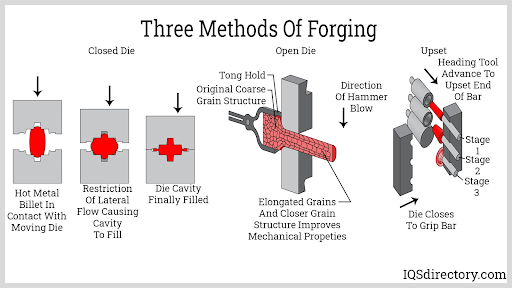
A. Open Die Forging
Open die forging compresses metal between flat or simple dies without enclosing it completely.
Best For:
- Large shafts
- Discs
- Rings
- Heavy-duty components
Design Characteristics:
- Simpler geometry
- Larger tolerances
- Requires significant machining
- No intricate cavities
Open die forgings prioritize strength over fine detail.
B. Closed Die Forging (Impression Die Forging)
Closed die forging shapes heated metal inside precision-machined cavities.
Best For:
- Automotive components
- High-volume production
- Near-net shape parts
Design Requirements:
- Draft angles are mandatory
- Fillets must be optimized
- Controlled flash formation
- Accurate parting line placement
Closed die forging delivers better repeatability but demands disciplined design planning.
C. Hot vs Cold Forging (Design Differences)
| Parameter | Hot Forging | Cold Forging |
|---|---|---|
| Temperature | Above recrystallization | Room temperature |
| Tolerance | Moderate | High |
| Surface Finish | Oxidation possible | Excellent |
| Design Complexity | More forgiving | Highly controlled |
Cold forging requires tighter design control and smoother transitions, while hot forging allows more flexibility but demands machining allowances.
Select the Right Forging Process Before Tooling
Choosing the wrong forging method can increase cost by 20–40%.
Manufyn helps you:
- Compare open vs closed die feasibility
- Evaluate batch volume impact
- Optimize geometry for chosen process
- Reduce tooling investment risk
Talk to Manufyn’s engineering team before locking your forging process. The right process starts with the right design.
Core Forging Design Rules (Engineering Best Practices)
This is the foundation of successful forging. If these principles are ignored, defects, die failures, and cost overruns are almost guaranteed.
Designing for forging is about controlling metal flow, minimizing stress concentration, and ensuring smooth die release.
Draft Angles in Forging Design
Draft angle in forging is a slight taper provided on vertical surfaces to allow smooth removal of the part from the die cavity.
Without sufficient draft:
- Parts stick inside the die
- Surface damage increases
- Die wear accelerates
- Production slows down
Standard Draft Angle Guidelines:
- External surfaces: 5°–10°
- Internal surfaces: 3°–7°
- Deep cavities require larger draft
Proper draft improves manufacturability, extends die life, and reduces rejection rates.
Fillet Radius in Forging
Fillets and radii in forging design are rounded transitions between surfaces that improve metal flow and reduce stress concentration.
Sharp corners restrict material flow and increase die cracking risk.
Best Practices:
- Avoid sharp 90° corners
- Increase radius with section thickness
- Use generous transitions at junctions
Proper fillets reduce forging defects, improve fatigue life, and lower tooling stress.
Parting Line in Forging
The parting line is the interface where the upper and lower dies meet. Its placement directly impacts flash formation and die complexity.
Poor parting line design increases trimming effort and material waste.
Design Recommendations:
- Keep parting lines flat and simple
- Align with maximum projected area
- Avoid unnecessary contours
Optimized parting lines reduce flash, improve dimensional control, and simplify tooling.
Section Thickness in Forging
Uniform section thickness ensures consistent metal flow and prevents defects like laps and incomplete filling.
Sudden thickness changes cause internal flow turbulence and stress concentration.
Recommended Approach:
- Maintain gradual transitions
- Avoid deep, thin ribs
- Use smooth tapers
Consistent geometry improves forging reliability and mechanical performance.
Validate Your Forging Design Before Tooling
Most forging failures are design-driven — not process-driven.
Manufyn’s engineering team reviews:
- Draft adequacy
- Radius optimization
- Parting feasibility
- Section uniformity
- Cost impact
Reduce risk. Improve strength. Optimize cost from the design stage. Request a Forging DFM Review from Manufyn before cutting dies.
Material Selection in Forging Design
Material selection in forging affects forgeability, die wear, mechanical strength, and total lifecycle cost. The right alloy improves flow behavior and reduces tooling stress.
Carbon Steel Forgings
Carbon steel is the most commonly used forging material due to its good forgeability and cost efficiency.
- Balanced strength and ductility
- Suitable for automotive and structural parts
- Lower raw material cost
Alloy Steel Forgings
Alloy steels provide higher fatigue strength and wear resistance for high-load components.
- Used in gears and crankshafts
- Better hardenability
- Requires tighter forging control
Alloy steels may increase die stress if geometry is complex.
Stainless Steel Forgings
Stainless steel forgings are selected for corrosion resistance and durability.
- Higher forging temperature required
- Increased die wear
- Requires generous draft and radii
Proper geometry is critical for stainless forging success.
Aluminum Forgings
Aluminum forgings offer a high strength-to-weight ratio and are widely used in automotive and aerospace industries.
- Lightweight
- Good machinability
- Excellent corrosion resistance
Design must account for thermal expansion and controlled draft angles.
Select the Right Forging Alloy with Manufyn
Choosing the wrong material can increase tooling cost and rejection rates.
Manufyn helps you:
- Compare alloy alternatives
- Evaluate forgeability risk
- Optimize geometry for selected material
- Reduce total manufacturing cost
Consult Manufyn before finalizing your forging material specification.
Designing Forgings for Cost Optimization
Most people say “reduce material” or “simplify geometry.”
That’s surface-level advice.
In reality, forging cost is driven by three hidden design multipliers:
- Projected area
- Material flow resistance
- Tooling stress concentration
If you optimize these at the design stage, total lifecycle cost drops significantly.
Projected Area Drives Press Tonnage & Cost
Projected area is the 2D shadow of the part when viewed from the die opening direction.
Why it matters:
- Larger projected area = higher press tonnage required
- Higher tonnage = higher machine cost
- Higher tonnage = increased die stress
Design Insight:
Two parts with identical weight can have drastically different costs if one has wider projected area.
Optimization Strategy:
- Avoid unnecessary flanges
- Minimize broad flat surfaces
- Reduce excessive width
Smart projected area reduction lowers press size requirement and improves die life.
Geometry That Respects Metal Flow
Forging is not about cutting material — it is about displacing it.
Designs that resist flow increase:
- Internal laps
- Incomplete fill
- Die wear
- Energy consumption
Common High-Cost Features:
- Deep narrow ribs
- Thin tall walls
- Sudden 90° cross-section transitions
- Long unsupported cavities
Instead:
- Guide metal gradually
- Use smooth radii
- Maintain balanced thickness
When geometry works with flow instead of against it, defect rate drops and cycle time improves.
Tooling Stress Concentration = Hidden Lifetime Cost
Sharp geometry not only affects the part — it directly impacts the die.
High-stress die regions cause:
- Micro-cracking
- Early die failure
- Frequent re-polishing
- Production stoppage
Tooling is one of the highest upfront costs in closed die forging.
Designing to reduce die stress increases:
- Tool life
- Batch size before rework
- Production stability
This is where design directly influences long-term ROI.
Design for Total Lifecycle Cost — Not Just Piece Price
At Manufyn, we evaluate forging designs for:
- Projected area efficiency
- Flow feasibility
- Die stress exposure
- Long-term tooling sustainability
The cheapest part on paper is rarely the cheapest over its lifecycle. Get a Cost-Oriented Forging Design Review from Manufyn before tooling investment.
Forging vs Casting vs Machining: Engineering Trade-Offs (Beyond Strength)
Most comparisons focus only on strength. That’s incomplete. The real decision depends on load path, volume, geometry complexity, and lifecycle expectation.
Forging vs Casting
Forging produces aligned grain flow, while casting creates random grain structure with possible internal porosity.
| Factor | Forging | Casting |
|---|---|---|
| Grain Structure | Directional | Random |
| Fatigue Strength | High | Moderate |
| Impact Resistance | Excellent | Lower |
| Internal Defects | Minimal | Possible porosity |
| Tooling Cost | High upfront | Moderate |
When Forging Wins:
- High dynamic load
- Fatigue-critical components
- Safety-critical applications
When Casting Wins:
- Complex internal cavities
- Low-load components
- Intricate geometries
Forging is chosen for reliability. Casting is chosen for geometric freedom.
Forging vs Machining from Billet
Machining from billet wastes material and eliminates natural grain alignment.
| Factor | Forging | Machining |
|---|---|---|
| Material Utilization | Efficient | High waste |
| Grain Direction | Optimized | Cut randomly |
| Strength-to-Weight | Higher | Lower |
| Cost at High Volume | Lower | Higher |
Machining is flexible for low volume and prototyping.
Forging becomes superior at scale.
Strategic Decision Insight
The right process depends on:
- Load orientation
- Volume forecast
- Cost sensitivity
- Failure risk tolerance
Process selection is not just a manufacturing decision — it is a performance decision.
Talk to Manufyn about the right process for your component — not just the obvious one.
Forging Design Checklist (Engineering Pre-Tooling Review)
Before releasing a forging drawing for die manufacturing, every design should pass a structured DFM validation.
Use this professional forging design checklist:
Geometry Validation
- Are draft angles applied to all vertical surfaces?
- Are internal and external radii sufficient for smooth metal flow?
- Is section thickness uniform with gradual transitions?
- Are deep ribs or thin walls avoided or validated?
- Is projected area optimized for press tonnage efficiency?
Tooling Feasibility
- Is the parting line simple and strategically placed?
- Is flash formation controlled and minimized?
- Are stress concentration zones reduced in die corners?
- Is die filling achievable without excessive forging load?
Material & Performance Alignment
- Is selected material suitable for geometry complexity?
- Is grain flow aligned with load direction?
- Is heat treatment compatible with design thickness?
- Are fatigue-critical regions supported by grain orientation?
Cost Optimization
- Is machining allowance minimized but sufficient?
- Is raw material utilization optimized?
- Is tooling life considered in geometry design?
- Has lifecycle cost been evaluated — not just piece price?
Why This Checklist Matters
Most forging failures are discovered after tooling investment.
At that stage, redesign becomes expensive and time-consuming.
Proactive design validation prevents:
- Die rework
- Production delays
- Excess scrap
- Field performance issues
Forging Design FAQs
What are the basic forging design rules?
Basic forging design rules include providing adequate draft angles, using generous fillets, maintaining uniform section thickness, optimizing parting line placement, and aligning grain flow with load direction. These principles ensure proper metal flow, longer die life, and reduced defects.
Why are draft angles required in forging?
Draft angles allow the forged component to be removed from the die without sticking or damaging the cavity. Insufficient draft increases die wear, ejection force, and surface defects.
How do fillets improve forging performance?
Fillets reduce stress concentration and improve material flow during forging. Rounded transitions prevent laps, reduce die cracking, and increase fatigue resistance in the final component.
Is forging stronger than casting?
Yes. Forging produces directional grain flow aligned with the part geometry, resulting in higher fatigue strength, impact resistance, and structural reliability compared to casting.
Can complex shapes be forged?
Complex shapes can be forged, but geometry must support proper metal flow. Deep narrow cavities and sharp corners may increase tooling cost and defect risk. Design optimization is required for complex forgings.
What tolerances are achievable in forging?
Tolerance capability depends on process type. Closed die forging offers moderate dimensional accuracy, while precision cold forging can achieve tighter tolerances. Machining is typically required for critical surfaces.
When should forging be chosen over machining?
Forging is preferred for high-volume production, fatigue-critical components, and parts requiring superior mechanical properties. Machining from billet is better suited for low volume or prototype production.