
Prototype Surface Finish: Types, Ra Values and Inspection
Surface finish is more than appearance. It influences friction, sealing, dimensional accuracy, coating performance and how reliably a prototype represents the final product.
Learn how to select a suitable surface finish for CNC machined metal parts, plastic prototypes and low volume manufactured components.
This guide explains surface roughness, common finishing methods, inspection techniques and the engineering decisions that affect prototype quality and cost.
Explore Finish Types Understand Inspection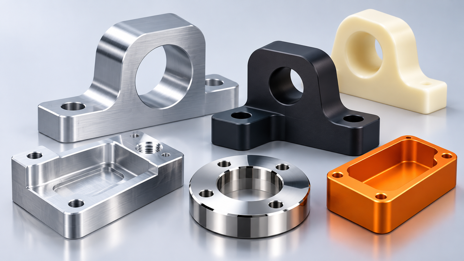
Understanding surface texture before prototype validation helps prevent finishing and inspection issues.
What Is Prototype Surface Finish?
Prototype surface finish describes the texture and surface condition of a manufactured component after processes such as CNC machining, additive manufacturing, injection molding, sanding, polishing or coating.
Surface finish requirements vary with the purpose of the prototype. A housing used for a design presentation may need a uniform cosmetic appearance. A sealing face may need controlled roughness and flatness. A sliding component may require a finish that supports predictable friction and wear.
The first step is to understand the distinction between surface roughness, waviness and surface defects. These characteristics are related, but they are not interchangeable.
Surface roughness
Roughness describes relatively fine variations in a surface profile. It can result from cutting tool marks, abrasive processing, material behavior or the finishing method used.
Surface waviness
Waviness refers to more widely spaced surface variations. Machine vibration, workholding, deflection and process instability can contribute to waviness even when local roughness is acceptable.
Surface defects
Scratches, burrs, dents, pits, embedded media and coating imperfections may affect quality independently of the measured roughness value.
Understanding Ra Values in Surface Finish
Ra, or arithmetic average roughness, is one of the most commonly specified surface texture parameters in engineering drawings. It represents the arithmetic average of the absolute deviations of a measured surface profile from its mean line over the evaluation length.
Ra is usually expressed in micrometers (µm) or microinches (µin). A smaller Ra value generally indicates a smoother measured profile, but it does not fully describe the shape or direction of every surface feature.
| Ra in µm | Approximate Ra in µin | General interpretation |
|---|---|---|
| 6.3 | 248 | Relatively coarse surface texture |
| 3.2 | 126 | Common general machining finish |
| 1.6 | 63 | Finer machined surface |
| 0.8 | 32 | Fine surface texture |
| 0.4 | 16 | Very fine surface texture |
| 0.2 | 8 | Fine finish requiring suitable process control |
These values are reference points for understanding roughness, not guaranteed results for a particular process. Actual capability depends on material, geometry, tooling, machine condition and measurement method.
Does a lower Ra always mean a better surface?
No. A smooth surface may be necessary for a seal, bearing interface or precision sliding application. Other applications may benefit from a controlled texture that supports coating adhesion or another functional requirement.
Ra should therefore be selected according to the function of the surface rather than simply specifying the smallest achievable value. Where surface profile shape, isolated peaks or directional marks matter, additional parameters and visual criteria may be necessary.
For further reading, see the CNC machining knowledge resources and the applicable surface texture standards referenced by your engineering drawing.
Common Types of Prototype Surface Finish
The appropriate finishing route depends on the base material, component geometry, required appearance, functional performance and inspection criteria.
| Finish | Typical characteristics | Common application | Key consideration |
|---|---|---|---|
| As machined | Visible tool marks | Functional prototypes and internal components | Finish depends on cutting parameters and tooling. |
| Fine machining | Reduced tool marks | Precision components and mating surfaces | Requires appropriate tools and stable machining. |
| Deburring | Removal of unwanted sharp edges and burrs | Holes, slots and machined edges | Must not damage critical dimensions. |
| Bead blasting | Uniform matte appearance | Aluminum housings and cosmetic parts | Media and process settings affect texture. |
| Polishing | Reduced roughness and improved reflectivity | Selected metal and plastic surfaces | May alter edges and dimensions. |
| Anodizing | Protective oxide layer on suitable aluminum alloys | Brackets, housings and fixtures | Underlying tool marks can remain visible. |
| Plating | Deposited metallic coating | Functional or decorative components | Coating buildup and material compatibility matter. |
| Painting or powder coating | Colored protective finish | Enclosures and external components | Define coverage, thickness and masking requirements. |
| Plastic surface finishing | Method dependent texture or appearance | Molded, machined or printed polymer parts | Heat and chemicals can affect the polymer. |
Surface Finish in CNC Machined Prototypes
CNC machined parts develop their initial surface texture during milling, turning, drilling and other cutting operations. Tool geometry, feed rate, cutting speed, machine rigidity and material properties all influence the result.
Tool selection and condition
Tool wear, edge geometry, runout and unsuitable cutting tools can increase surface marks or create inconsistent finishes. Material selection also matters because different alloys and engineering plastics respond differently to cutting forces and heat.
Feed rate and cutting parameters
Feed rate and cutting conditions influence the geometry of tool marks. A finishing pass with suitable parameters may improve the surface, but the result must be validated against the material, toolpath and machine capability.
Workholding and vibration
Poor workholding, tool deflection and vibration can create chatter marks or uneven surfaces. Thin walls, deep pockets and long tool extensions can make these problems more difficult to control.
Finishing after machining
Deburring, blasting or polishing may be suitable when the initial machining process cannot deliver the desired result. However, secondary finishing can affect edge radii, coating interfaces and dimensional tolerances.
Explore the CNC machining knowledge base for related information about tooling, workholding, dimensional control and machining processes.
How Material Selection Affects Prototype Finishing
Aluminum alloys
Aluminum is widely used for lightweight prototype components. Machining marks, alloy selection, blasting conditions and anodizing requirements influence the final appearance. If a uniform cosmetic result is important, agree on the pre-treatment and final acceptance standard before production.
Stainless steel
Stainless steel finishing may involve controlled machining, deburring, polishing or suitable surface treatments. Heat generation, tool wear and corrosion requirements must be considered during process planning.
Engineering plastics
ABS, polycarbonate, nylon, PEEK and other engineering plastics require process-specific finishing methods. Excessive heat can distort a component, while incompatible solvents may damage certain polymers. Glass-filled materials can also expose fibers during machining or abrasion.
Steel and other metals
Carbon steel may require corrosion protection after machining. Copper and brass can develop burrs or surface smearing, while harder alloys may require specialized tooling and finishing parameters.
Related resources: Manufyn Resource Hub, rapid prototyping and prototype injection molding.
How to Inspect Prototype Surface Finish
Surface inspection should be based on the engineering drawing and the intended function of the part. A visual check alone cannot confirm a specified Ra value, and a roughness measurement cannot establish that every cosmetic defect is acceptable.
| Inspection requirement | Suitable method | What to verify |
|---|---|---|
| Surface roughness | Contact profilometer or suitable optical instrument | Specified parameter, measurement location and acceptance limit |
| Dimensions | Micrometer, bore gauge, CMM or other suitable instrument | Critical dimensions before or after finishing as specified |
| Visual appearance | Defined visual inspection standard | Scratches, dents, discoloration, tool marks and coating defects |
| Coating thickness | Suitable coating thickness measurement method | Thickness, coverage and masking of critical interfaces |
| Material and treatment | Material certificates and process documentation | Material identity and compliance with specified treatment |
Why measurement conditions matter
Roughness results can vary with the instrument, probe, cutoff, evaluation length, measurement direction and surface geometry. The inspection method should be appropriate for the drawing requirements and the applicable standard.
For curved, narrow or inaccessible surfaces, the selected instrument may not be suitable for direct measurement. Agree on a practical verification method before manufacturing begins.
Inspection before and after finishing
A useful inspection plan identifies which characteristics must be checked after machining and which must be checked after the final coating or surface treatment. This is particularly important where coating thickness, masking or material removal can affect critical dimensions.
Explore related information in our manufacturing case studies and manufacturing blogs.
What Determines Prototype Surface Finishing Cost?
Surface finishing cost depends on more than the specified Ra value. The material, geometry, quantity, process sequence and inspection requirements all influence the final quotation.
- Required surface quality: Finer roughness requirements can need additional machining, polishing or verification.
- Material: Hardness, abrasiveness, thermal behavior and machinability affect cycle time and tool consumption.
- Geometry: Deep pockets, internal features, thin walls and difficult-to-reach surfaces can increase finishing effort.
- Surface area: Larger parts may need more time for blasting, coating, polishing and handling.
- Masking: Threads, precision bores, sealing faces and electrical contact surfaces may require protection during treatment.
- Quantity: Setup and handling costs are distributed differently between a single prototype and a repeat production batch.
- Inspection: Profilometry, dimensional reports, traceability and special documentation can add cost.
During RFQ evaluation, separate mandatory functional requirements from cosmetic preferences. This helps avoid specifying expensive finishing operations on surfaces where they provide no meaningful engineering benefit.
How to Specify Prototype Surface Finish on a Drawing
An effective drawing communicates the required surface condition clearly enough for manufacturing and quality teams to plan the process and verify the finished component.
- Identify the surface or feature that requires a controlled finish.
- Specify Ra or another relevant surface texture parameter and its limit.
- Reference the applicable drawing standard.
- Define mandatory finishing processes, if any.
- Identify surfaces that must be masked or remain untreated.
- Specify coating requirements, including thickness and coverage where applicable.
- Define the measurement method or inspection acceptance criteria.
- State whether the dimensions and surface requirements apply before or after finishing.
Do not assume that a surface roughness symbol communicates every cosmetic requirement. Where appearance is critical, include a reference sample, visual standard or explicit acceptance criteria.
Drawing requirements should reflect the actual function of the component. Tight roughness limits on non-critical surfaces can increase cost without improving product performance.
From Prototype Surface Finish to Repeatable Production
A manually polished prototype may meet a cosmetic requirement, but repeat production needs a controlled and repeatable process. The finishing route should be reviewed before the design moves into low-volume or serial production.
01. Define requirements
Establish the material, geometry, surface parameters, appearance requirements and intended use of the prototype.
02. Select the process
Evaluate machining, polishing, blasting, coating or other suitable finishing methods for the component.
03. Validate the sample
Inspect the prototype against dimensional, roughness and visual acceptance requirements.
04. Standardize production
Document the finishing sequence, masking requirements, inspection method and acceptance criteria before repeat manufacturing.
Where applicable, automotive programs may require additional customer-specific quality documentation, APQP or PPAP. These requirements should be agreed with the customer at the appropriate stage of the project.
Related Manufacturing Knowledge and Resources
Surface finish decisions connect to machining strategy, material selection, inspection planning and supplier process capability. The following Manufyn resources provide additional context for engineers and procurement teams.
Frequently Asked Questions About Prototype Surface Finish
What is the best surface finish for a prototype?
The best finish depends on the application. An as-machined surface may be sufficient for an internal functional prototype, while a polished, blasted or coated surface may be needed for a specific cosmetic or functional requirement.
What does Ra mean in surface finish?
Ra is the arithmetic average roughness of a measured surface profile. It is normally expressed in micrometers or microinches. It does not fully describe waviness, isolated defects or the direction of machining marks.
What Ra value can CNC machining achieve?
Achievable roughness depends on the machine, material, tooling, cutting parameters, geometry and inspection method. Confirm the required value with the manufacturer rather than assuming one universal capability.
Does anodizing remove CNC machining marks?
No. Anodizing forms an oxide layer on aluminum but does not inherently eliminate the underlying machining texture. A suitable pre-treatment may be necessary to achieve the intended appearance.
Is bead blasting suitable for precision prototype parts?
It can be suitable when a uniform matte appearance is required. However, blasting can change surface texture and may affect sensitive features. Mask critical interfaces where necessary and define the acceptance criteria.
Can engineering plastic prototypes be polished?
Many plastics can be polished or otherwise finished, but the suitable process depends on the polymer, geometry and manufacturing method. Heat and chemical compatibility must be considered.
How should surface finish be inspected?
Use a suitable profilometer or optical instrument when a numerical roughness requirement applies. Visual inspection is useful for cosmetic defects, while dimensional instruments verify geometry and tolerances.
What should be included in a prototype finishing RFQ?
Include the CAD model, engineering drawing, material, quantity, surface finish requirements, coating and masking instructions, inspection requirements, documentation needs and delivery destination.
Making Better Prototype Manufacturing Decisions
Understanding surface finish helps engineers communicate design intent, select suitable manufacturing processes and establish practical inspection requirements before production begins.
Manufyn supports international procurement projects involving manufacturing suppliers in India, including prototype coordination, supplier communication, quality follow-up and delivery management. Feasibility depends on the component, material, specifications and supplier capabilities.
Discuss Your Manufacturing Requirements