
Optical Inspection in Manufacturing: Methods, Accuracy and Applications
Optical inspection helps manufacturers examine component geometry, measure visible features and identify surface defects using light based imaging systems. Understand how optical measurement works, where it fits into quality control and when another inspection method may be more suitable.
What Is Optical Inspection?
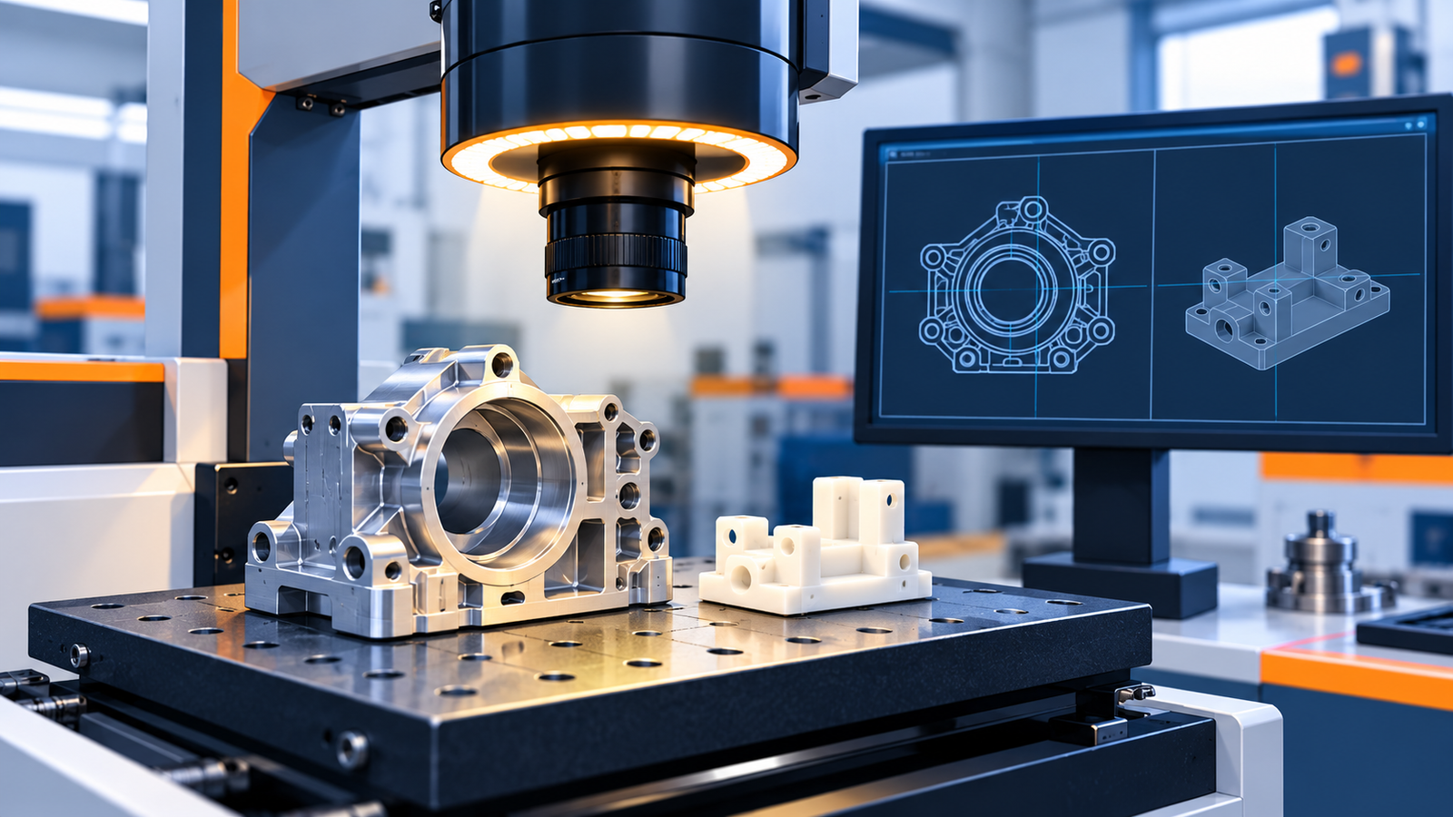
Optical inspection is a group of techniques that use light, lenses, cameras and image processing to examine a manufactured component without necessarily contacting its surface.
Depending on the equipment, optical inspection can identify visible defects, examine component profiles or measure dimensions such as hole diameters, center distances, widths, radii and angles. It is used in precision machining, injection molding, electronics, sheet metal manufacturing and prototype development.
The term covers several different technologies. A conventional inspection camera may detect a missing feature or surface defect, while a calibrated vision measuring machine can measure selected dimensions. These capabilities should not be treated as equivalent.
Optical inspection and automated optical inspection
Automated optical inspection (AOI) typically uses cameras, controlled lighting and software to identify predefined defects or verify assembly conditions. Optical metrology focuses on measuring dimensions and geometric characteristics. Some systems perform both tasks, but their acceptance criteria should be defined separately.
How Does Optical Inspection Work?
A typical optical measurement procedure begins with a defined drawing requirement and ends with documented measurement results. The exact procedure depends on the equipment and the features being inspected.
- Prepare the part Clean the component and confirm its drawing revision, condition and identification.
- Position and illuminate Establish a repeatable position and choose suitable lighting to reveal the required features.
- Capture and measure Acquire images, establish references and measure the specified characteristics.
- Evaluate and record Compare results with drawing requirements and document acceptance or nonconformities.
Why lighting and positioning matter
Backlighting is useful for examining silhouettes and through holes, while reflected lighting can reveal surface features. Reflective metals, transparent plastics, burrs and complex contours may require different illumination arrangements.
Part alignment is equally important. Incorrect positioning, tilt or datum selection can produce misleading results. Repeatable fixtures and documented measurement programs help reduce variation between operators and inspection cycles.
Types of Optical Inspection Systems
Different systems serve different purposes. Select the method based on the feature geometry, measurement requirement, inspection volume and required documentation.
1. Optical Comparator
Projects a magnified silhouette of a component for profile comparison and measurement.
Applications: Two dimensional profiles, radii, angles, stamped parts and visible contours.
Consideration: A conventional profile projector does not directly measure every three dimensional or hidden feature.
2. Vision Measuring Machine
Uses a camera, precision stage and software to measure image defined features, often through programmed routines.
Applications: Hole spacing, center distances, small machined features and plastic component profiles.
Consideration: Capability depends on optics, calibration, field of view and measurement setup.
3. Automated Optical Inspection
Uses image processing to detect predefined defects, missing features or assembly conditions.
Applications: Electronics, assembly verification and high volume production inspection.
Consideration: Detection performance must be validated using representative good and defective parts.
4. Optical Microscopy
Magnifies local areas to examine surface details and small component features.
Applications: Burrs, scratches, tool marks, edge damage and failure investigations.
Consideration: Magnification alone does not establish dimensional accuracy or surface roughness.
Applications of Optical Inspection in Manufacturing
CNC machined metal components
Optical measurement can verify accessible hole diameters, slot widths, radii, center distances and two dimensional profiles. It is particularly useful when a component contains several small features that need to be checked against an engineering drawing.
For complex three dimensional geometry, deep bores or certain GD&T requirements, a CMM or another suitable instrument may be necessary.
Injection molded plastic components
Optical systems can examine molded profiles, openings, connector features and visible dimensional characteristics. Non contact measurement can be advantageous when a flexible plastic part might deform under probe pressure.
Material shrinkage, moisture, temperature, transparency and part stability must still be considered when interpreting results.
Sheet metal and stamped parts
Flat profiles, cutouts, slots and hole locations are often suitable for optical inspection. Backlighting can improve visibility of the perimeter, although burrs and reflective edges can influence edge detection.
Prototypes and first article inspection
Optical measurement can help identify dimensional deviations before a design enters repeat production. Inspection plans should prioritize dimensions that influence fit, function, assembly and downstream manufacturing.
Related reading: Prototype Inspection , Prototype Quality Control and First Article Inspection .
Optical Inspection Accuracy and Tolerances
There is no single accuracy value that applies to every optical inspection system. Performance depends on the instrument, optics, calibration, feature geometry, surface condition, environmental stability and measurement procedure.
Factors that influence measurement results
- Optical resolution: The system must resolve the feature sufficiently for the required measurement.
- Edge detection: Shadows, reflections, chamfers and burrs can affect the identified boundary.
- Field of view: Coverage and feature resolution depend on the optical configuration.
- Calibration: Reference standards and suitable verification procedures support measurement reliability.
- Temperature: Thermal expansion can affect dimensions of metal and polymer components.
- Datum alignment: Incorrect references can create misleading dimensional comparisons.
- Measurement uncertainty: The measurement method must be suitable for the tolerance and acceptance decision.
What should an optical inspection report include?
- Part number and engineering drawing revision.
- Sample identification and inspection date.
- Characteristic or drawing reference number.
- Nominal dimension and tolerance limits.
- Actual measured values and units.
- Acceptance status and nonconformance details.
- Equipment and method identification, where required.
Optical Inspection vs CMM Inspection
A tactile coordinate measuring machine uses a probe to collect coordinate points, while optical metrology derives measurements from images or other light based sensors. Neither method is automatically suitable for every drawing requirement.
| Criteria | Optical Measurement | Tactile CMM |
|---|---|---|
| Measurement principle | Image, silhouette or optical sensor data | Probe based coordinate measurement |
| Delicate components | Useful where contact could deform the part | Probe force and support require consideration |
| Flat profiles and visible edges | Often efficient for suitable features | Can measure with an appropriate program |
| Deep or hidden features | May be limited by line of sight | Depends on probe access and geometry |
| Complex 3D geometry | Depends on sensors and system configuration | Suitable for many coordinate and GD&T tasks |
| Best selection criterion | Verified capability for the required features | Verified capability for the required features |
Both methods can be used in the same inspection plan. For example, optical measurement may be used for hole spacing and flat profiles, while a CMM checks selected three dimensional characteristics.
Further reading: CNC Machining Tolerances and CNC Machining .
Limitations and Common Optical Inspection Errors
Optical inspection can produce misleading results when the equipment or measurement procedure is not suited to the component. Common issues include:
- Reflective surfaces: Glare can obscure the actual component edge.
- Transparent materials: Refraction and reflections can complicate edge identification.
- Burrs and sharp edges: The detected boundary may not match the intended drawing feature.
- Hidden geometry: Internal passages and obstructed surfaces may not be optically accessible.
- Incorrect alignment: Poor positioning or datum selection can distort the measurement.
- Uncontrolled conditions: Temperature, vibration and inconsistent fixturing can affect results.
- Unvalidated detection rules: Automated systems may miss defects or reject acceptable parts.
How to reduce inspection errors
Use a documented work instruction, repeatable fixturing, appropriate illumination, verified calibration and defined measurement settings. Validate the method against representative parts and the actual acceptance criteria before using it for production release.
Optical Inspection in Prototype Quality Control
Prototype inspection should verify drawing requirements rather than relying only on visual appearance. Each characteristic should be connected to an appropriate measurement method.
- Review the latest drawing and identify critical dimensions, datums and geometric tolerances.
- Select optical or alternative measurement methods for each characteristic.
- Verify calibration status, fixture repeatability and part measurement conditions.
- Record actual measurements and compare them with the specified tolerance limits.
- Investigate deviations and distinguish manufacturing defects from setup or measurement issues.
- Release the agreed inspection report and supporting quality documentation.
For international buyers purchasing prototype parts from India, a defined inspection plan can make acceptance criteria clearer and reduce the risk of discovering fit or dimensional problems after shipment.
Explore the related Manufacturing Knowledge Hub for more practical engineering guides.
Frequently Asked Questions About Optical Inspection
1. What is optical inspection in manufacturing?
Optical inspection uses light based imaging and measurement systems to examine part appearance, geometry or dimensions. It can range from visual defect detection to dimensional metrology.
2. Is optical inspection a non contact measurement method?
Optical measurement typically does not require a probe to touch the measured surface. The component must still be supported and positioned appropriately.
3. Can optical inspection measure tight tolerances?
Some calibrated optical systems can measure very tight tolerances. Suitability depends on verified instrument performance, feature geometry, uncertainty and measurement conditions.
4. What is the difference between an optical comparator and a VMM?
An optical comparator primarily projects and measures a component profile. A vision measuring machine uses cameras, precision stages and software to measure image defined features.
5. Can optical inspection be used for plastic components?
Yes. It can be useful for molded and machined plastics, especially where contact pressure may deform the part. Material stability, transparency and temperature must also be considered.
6. Does optical inspection replace CMM inspection?
Not in every application. Optical systems are useful for many visible profiles and dimensions, while tactile CMMs can be better suited to accessible three dimensional features and certain GD&T requirements.
7. What information is needed for prototype inspection?
Typically, the latest engineering drawing, part number, nominal dimensions, tolerances, datum references, sample quantity and required report format are needed.
Understanding Inspection Starts With the Drawing
Before selecting an inspection system, define the features, tolerances, datums and acceptance criteria that matter to the component. A suitable measurement method should support the engineering requirement, not simply produce an image or a list of dimensions.
Explore More Engineering GuidesTechnical note: Inspection capabilities vary by equipment, component geometry and measurement conditions. Always validate the selected method against the engineering drawing and applicable acceptance requirements.