
Flatness in Prototype Parts: GD&T, Tolerances and Inspection
How to understand, specify, manufacture and inspect flat surfaces in CNC machined and other prototype components.
Flatness affects assembly fit, sealing, alignment and functional testing. This engineering guide explains the tolerance zone, drawing interpretation, manufacturing challenges and inspection methods used to evaluate flatness in prototype parts.
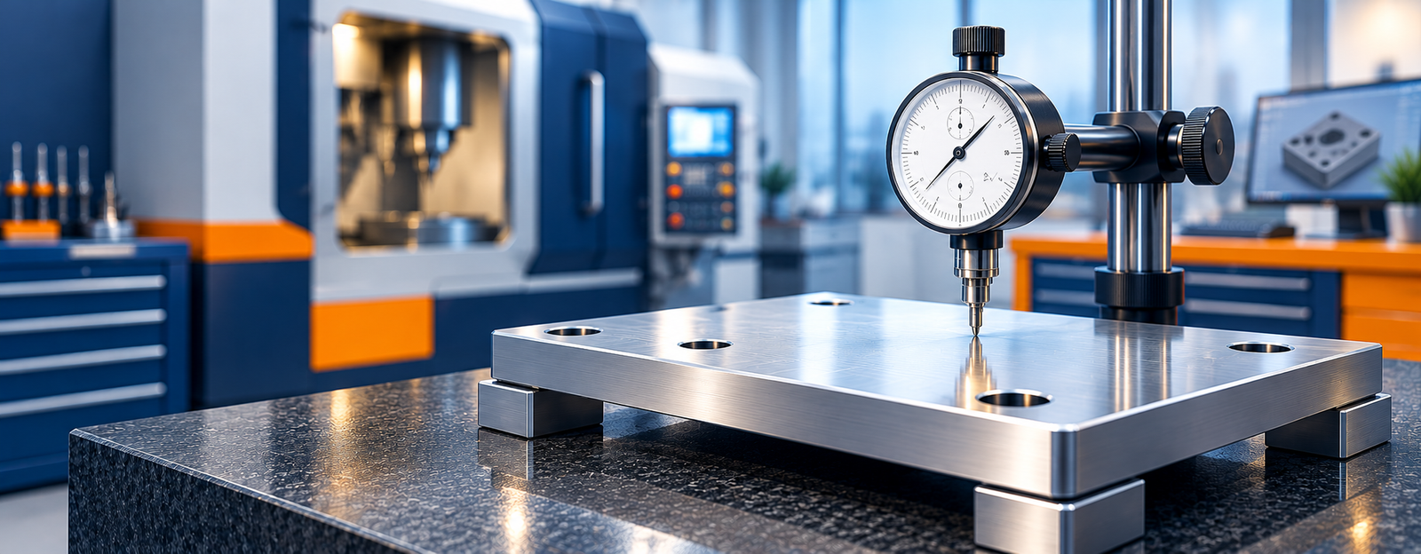
In prototype development, a component can meet its length, width and thickness dimensions yet still fail to sit correctly against a mating part. The reason may be surface distortion, bowing or twisting that is not adequately described by size dimensions alone.
Flatness in GD&T defines how much an individual surface may deviate from a theoretically perfect plane. Understanding this control helps mechanical engineers communicate functional requirements and helps manufacturing teams choose appropriate machining, finishing and inspection methods.
1. What Is Flatness in Prototype Parts?
Flatness is a GD&T form control that limits the variation of an individual surface from a perfect plane. The complete controlled surface must fit within two parallel planes separated by the specified tolerance.
Unlike controls that establish orientation or location relative to another feature, flatness evaluates the form of the surface itself. It does not require a datum reference.
Flatness may be important on mounting plates, machined brackets, machine bases, fixture plates, housings and sealing faces. Its importance depends on the part’s functional requirements, rather than on whether the surface looks visually flat.
2. Flatness Symbol and Tolerance Zone
The flatness symbol in engineering drawings is a parallelogram. It appears in a feature control frame with a numerical tolerance value. The symbol and tolerance should be interpreted according to the applicable drawing standard, such as ASME Y14.5 or ISO 1101.
Example: A flatness tolerance of 0.05 mm
A flatness tolerance of 0.05 mm means that the controlled surface must fit between two parallel planes with a separation of 0.05 mm. The surface can have some variation, but the total separation of the applicable tolerance planes must not exceed the stated value.
This does not mean that every individual measurement must be within 0.05 mm of a single arbitrarily selected height. Flatness evaluates the surface as a whole, using the applicable geometric evaluation method.
Does flatness require a datum?
No. Flatness is a form tolerance and does not require a datum. Parallelism, by contrast, controls orientation relative to a datum. If a component needs both a flat mounting face and a specific orientation to another surface, the drawing may need separate controls for those requirements.
3. Why Flatness Matters in Prototype Manufacturing
Assembly fit and alignment
Warped contact surfaces can cause rocking, uneven gaps and assembly misalignment. Flatness can be important for mounting plates, brackets, precision fixtures and mechanical housings.
Sealing performance
Flanges and sealing faces may need controlled flatness to provide consistent contact. However, flatness alone does not guarantee leak-free performance. Surface finish, gasket properties, mating geometry and clamping force must also be considered.
Functional testing
An uneven prototype may be supported or clamped differently during testing, changing its behavior. Appropriate geometric requirements help engineers evaluate the intended design rather than unintended distortion.
Prototype-to-production consistency
Establishing critical geometric requirements during prototype development helps manufacturing teams identify suitable processes and inspection methods before production quantities increase.
4. What Causes Flatness Errors?
Flatness problems can originate in raw material, machining, workholding, finishing, molding or inspection. Corrective action depends on the cause of the deviation.
| Cause | Potential effect | Manufacturing consideration |
|---|---|---|
| Residual material stress | Bowing or twisting after material removal | Review material condition, stock allowance and machining sequence. |
| Excessive clamping | Distortion during machining or inspection | Use suitable workholding and avoid unnecessary clamping force. |
| Uneven material removal | Changing stress distribution across the part | Consider roughing, intermediate checks and finishing passes. |
| Thermal effects | Expansion or dimensional changes | Manage cutting conditions and temperature during measurement. |
| Thin or unsupported geometry | Deflection during machining | Review support, stiffness and machining strategy. |
| Injection molding shrinkage | Warping after cooling | Review wall thickness, gating, cooling and process conditions. |
| Finishing or coating | Changes to surface form | Evaluate grinding, plating, coating and post-processing effects. |
Why machining sequence matters
Milling can release residual stresses in aluminum, steel and other materials. When material is removed unevenly, the remaining section may bend or twist. Thin plates and large pocketed parts can be especially sensitive.
Depending on the material and application, a suitable approach may include rough machining, intermediate inspection, stress management where appropriate, and a final finishing operation. The exact route should be determined from the part geometry, material condition and tolerance requirement.
5. How to Specify Flatness for Prototype Parts
Step 1: Identify the functional surface
Determine whether the controlled surface supports a component, forms a seal, locates an assembly or affects another functional requirement. Apply geometric controls where they are needed.
Step 2: Establish the tolerance
Define the acceptable form variation based on functional requirements and the applicable engineering standard. Avoid assigning an unnecessarily tight value without understanding its effect on manufacturing and inspection.
Step 3: Check other geometric requirements
Flatness does not control the orientation of a surface relative to a datum, the location of holes or the size of a feature. Specify additional controls when the design requires them.
Step 4: Review manufacturability
Review material grade, part dimensions, thickness, machining access, workholding, finishing operations and inspection capability before releasing the drawing.
Step 5: Define inspection requirements
Agree on the inspection method, evaluation criteria and reporting requirements before manufacturing. The chosen method must be appropriate for the tolerance and part geometry.
For additional drawing guidance, read GD&T for Prototypes and Datum Selection for Prototype Parts .
6. Flatness vs Parallelism vs Surface Profile
These controls address different geometric requirements. Selecting the correct one depends on what the design needs to control.
| GD&T control | What it controls | Datum required? | Typical use |
|---|---|---|---|
| Flatness | Form of an individual surface | No | Flat mounting or contact face |
| Parallelism | Orientation relative to a datum | Yes | Two surfaces that must maintain a parallel relationship |
| Surface profile | Deviation from a defined surface profile | Depends on the specified control | Complex contours and shaped interfaces |
A common drawing mistake is specifying flatness when the actual design requirement concerns the relationship between two surfaces. Identify the functional requirement before selecting the geometric control.
Related reading: Position Tolerance in Prototype Parts .
7. How Is Flatness Measured?
Inspection methods depend on part size, geometry, material, tolerance and required measurement confidence.
Surface plate and dial indicator
A dial indicator can be used to collect height readings across a suitable surface. The support arrangement and measurement procedure must avoid forcing the component flat. A simple indicator sweep may not, by itself, establish a complete flatness evaluation.
Coordinate measuring machine (CMM)
A CMM can collect three-dimensional surface points for evaluating flatness. Point distribution, probe strategy, surface accessibility and software evaluation affect the result. The measurement plan should be suitable for the geometry and specified tolerance.
Other metrology equipment
Height gauges and other suitable instruments may be used for selected inspection setups. Their suitability depends on the measurement strategy and whether the collected data can establish the required surface form.
8. Flatness Across Manufacturing Processes
CNC machining
Flatness depends on material stress, cutting strategy, workholding, component stiffness and finishing operations. Thin plates and pocketed components may require staged machining and careful support.
3D printing
Build orientation, cooling, support strategy and residual stress can influence warpage. A critical flat surface may require suitable post-processing or machining.
Prototype injection molding
Differential shrinkage, uneven wall thickness, gate placement, cooling and ejection can affect flatness. Design for manufacturability review helps identify potential warpage before tooling is finalized.
Grinding and secondary finishing
Grinding may improve flatness when appropriate for the material and geometry. Thermal effects, residual stress, support conditions and any subsequent coating or plating process must also be considered.
Explore the broader Manufyn Engineering Resource Hub for related manufacturing and engineering topics.
9. How Flatness Affects Cost and Lead Time
Tighter flatness requirements can increase machining time, inspection effort and rejection risk. Additional operations may be required where the material or geometry is prone to distortion.
- Material type, dimensions and material condition.
- Part thickness and unsupported spans.
- Required flatness tolerance.
- Machining sequence and finishing operations.
- Stress management and intermediate inspection.
- Inspection equipment and reporting requirements.
- Production quantity and repeatability requirements.
The most useful way to evaluate a prototype is to review the CAD model and engineering drawing together. This helps establish the manufacturing route, critical features and inspection requirements before quotation.
For practical manufacturing examples, browse Manufyn’s CNC Machining Case Study and the related Gear Manufacturing in India article .
10. From Prototype Validation to Production
Flatness requirements should be reviewed early enough for prototype inspection results to inform the next manufacturing stage. A useful workflow includes drawing review, prototype production, dimensional verification, functional testing and process refinement.
Documenting the manufacturing method and inspection criteria helps teams evaluate repeatability before increasing production volumes. The objective is to establish whether the process consistently satisfies the actual engineering requirement.
Related manufacturing case studies and practical articles can help engineers compare approaches and understand real-world production considerations. Treat every example in the context of its specific material, geometry and tolerance requirements.
Frequently Asked Questions
What is flatness in GD&T?
Flatness is a form tolerance that controls the variation of an individual surface. The complete surface must fit between two parallel planes separated by the specified tolerance.
Does flatness require a datum?
No. Flatness controls surface form independently and does not require a datum reference.
What is the difference between flatness and parallelism?
Flatness controls the form of an individual surface. Parallelism controls orientation relative to a datum.
How do you measure flatness on a CNC machined part?
Suitable methods include a surface plate and dial indicator, a CMM or other appropriate metrology equipment. The inspection strategy must characterize the surface without introducing distortion.
What causes flatness problems in prototype parts?
Common causes include residual material stress, excessive clamping, uneven material removal, thermal effects, thin unsupported geometry, molding shrinkage and finishing operations.
Can CNC machining achieve tight flatness tolerances?
Yes, depending on the part geometry, material, workholding, machining sequence, finishing process and inspection method. The achievable tolerance must be evaluated for the specific part.
Should every prototype surface have a flatness tolerance?
No. Specify flatness where surface form affects fit, sealing, alignment, support or functional performance. Unnecessary geometric controls may add cost without improving function.