Manufyn helps you scale from prototype to production.
Insert & Overmold Design Guide for Injection Molding
(Design, Bonding, Tooling & Manufacturing Services by Manufyn)
Insert molding and overmolding are manufacturing techniques used when single-material plastic parts cannot meet functional, structural, or assembly requirements. In production environments, these processes are chosen not for aesthetics alone, but to reduce part count, improve durability, and eliminate secondary assembly operations.
In insert molding, a pre-formed component—most commonly metal—is placed into the mold and encapsulated by plastic in a single injection cycle. In overmolding, a second plastic or elastomer is molded over an existing substrate to add grip, sealing, insulation, or protection. While the end result may look simple, the manufacturing complexity behind these processes is significantly higher than standard injection molding.
From a tooling and production standpoint, insert and overmolding decisions affect:
- mold complexity and cost
- cycle time and automation potential
- bonding reliability and field performance
- long-term maintenance and scrap rates
Poorly designed insert or overmolded parts frequently fail after tooling is built, not during CAD review. Common issues include insert movement, delamination, flash around shut-offs, and inconsistent bonding across production batches. These failures are expensive to correct once steel is cut.
At Manufyn, insert and overmolding are treated as manufacturing systems, not isolated design features. Geometry, material pairing, bonding method, tooling strategy, and production volume are evaluated together to ensure parts are production-ready, scalable, and reliable in real US manufacturing environments.
Designing a part that requires inserts or overmolding?
Manufyn supports insert and overmolding from design validation through US-based production.
What Is Insert Molding?
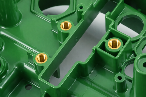
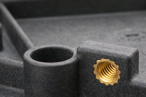
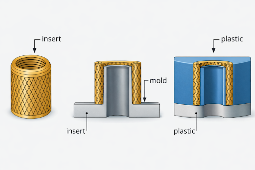
Insert molding is an injection molding process in which pre-manufactured components are placed into a mold cavity and plastic is molded around them, permanently integrating the insert into the finished part. Once molded, the insert cannot be removed without destroying the part.
In production, insert molding is most commonly used with:
- threaded metal inserts
- electrical contacts and terminals
- bushings, pins, and load-bearing reinforcements
- magnets or shielding components
The primary manufacturing advantage of insert molding is the elimination of secondary assembly operations. Instead of pressing, gluing, or fastening inserts after molding, insert molding integrates the component during the molding cycle, improving positional accuracy and long-term reliability.
However, insert molding also introduces specific engineering and tooling challenges. During injection, molten plastic exerts significant pressure on the insert. If the insert is not properly retained or fixtured, it can shift, rotate, or lift, leading to flash, dimensional inaccuracies, or internal stress concentration. Differences in thermal expansion between metal and plastic can further amplify stress during cooling.
Successful insert molding depends on:
- insert geometry with mechanical retention features
- controlled insert positioning and support in the mold
- sufficient plastic coverage around the insert
- tooling shut-offs that prevent flash without damaging the insert
Because of these constraints, insert molding design must be validated against injection pressure, shrinkage behavior, and long-term service loads, not just CAD geometry.
At Manufyn, insert molding designs undergo DFM review focused on insert stability, tooling feasibility, and production scalability, ensuring inserts remain secure throughout molding and across the full life of the mold.
Not sure if insert molding is the right solution for your part?
Manufyn reviews insert geometry, tooling strategy, and production feasibility early.
What Is Overmolding?
Overmolding is an injection molding process in which a secondary plastic or elastomer material is molded over an existing substrate to create a single integrated component. Unlike insert molding, where a rigid insert is embedded, overmolding focuses on adding functional surface layers or secondary material properties to an already formed part.
In production environments, overmolding is most commonly used to:
- improve grip and ergonomics (soft-touch surfaces)
- add sealing and environmental protection
- provide electrical insulation or vibration damping
- enhance aesthetics without secondary assembly
From a manufacturing standpoint, overmolding replaces operations such as adhesive bonding, press-fitting, or mechanical fastening. When executed correctly, overmolding produces stronger, more reliable bonds than post-assembly methods and significantly reduces part count.
However, overmolding introduces its own set of engineering challenges. The overmold material must flow uniformly over the substrate, bond consistently, and release cleanly from the mold. Poor overmold design often results in delamination, flash at shut-offs, air traps, or uneven surface finish, especially in elastomer overmolding.
Because of this, overmolding must be treated as a multi-material manufacturing system, where bonding mechanism, material compatibility, mold design, and production volume are evaluated together.
At Manufyn, overmolding strategies are selected based on bonding reliability, automation potential, and long-term production stability, not just visual appearance.
Planning a soft-touch, sealed, or multi-material part?
Manufyn supports overmolding design, tooling, and US-based production.
Overmolding vs. Insert Molding: Key Manufacturing Differences
Although insert molding and overmolding are often grouped together, they solve fundamentally different manufacturing problems. Selecting the wrong process can increase tooling cost, complicate production, or limit scalability.
Insert molding is used when a non-plastic component must be structurally or functionally integrated into a plastic part. Overmolding is used when a secondary plastic layer is required to modify surface behavior or performance.
From a production perspective, the decision is driven by function, bonding requirements, tooling complexity, and volume, not by visual similarity.
Manufacturing Comparison: Insert Molding vs. Overmolding
| Aspect | Insert Molding | Overmolding |
|---|---|---|
| Primary goal | Embed components | Add secondary material |
| Typical materials | Metal + plastic | Plastic + plastic / elastomer |
| Bonding mechanism | Mechanical / thermal | Mechanical + chemical |
| Tooling complexity | Medium | Medium to high |
| Common risks | Insert shift, stress | Delamination, flash |
| Automation readiness | High | Medium–High |
| Typical use cases | Threads, contacts | Grips, seals, housings |
Insert molding is generally easier to automate and scale, especially for threaded or load-bearing features. Overmolding offers greater functional flexibility but requires stricter control of bonding, flow, and shut-off design.
At Manufyn, this decision is made using a DFM-led evaluation, considering tooling cost, expected production volume, material behavior, and long-term reliability in US manufacturing environments.
Not sure whether insert molding or overmolding fits your part?
Manufyn helps choose the right process based on tooling, bonding, and production goals.
Overmolding Methods Used in Production
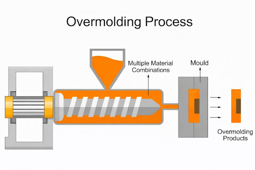
Overmolding can be executed using different production methods depending on volume, automation level, tooling investment, and bonding requirements. The two dominant methods used in commercial injection molding are pick-and-place overmolding and two-shot (2K) overmolding.
From a manufacturing standpoint, the choice of method determines:
- tooling and machine requirements
- cycle time and labor dependency
- bonding consistency
- scalability and cost per part
Choosing the wrong overmolding method early can lock a project into high labor cost or unstable quality later in production.
-
Pick-and-Place Overmolding
In pick-and-place overmolding, a pre-molded substrate is placed into a mold—either manually or using automation—and the overmold material is injected over it in a separate step.
This method is widely used for low-to-medium production volumes, prototypes, and early production runs because tooling cost is relatively low and design changes are easier to implement.
However, pick-and-place overmolding introduces handling variability. Misalignment, inconsistent contact pressure, and cycle interruptions are common risks—especially in manual operations. Automated pick-and-place reduces variability but adds equipment cost and integration complexity.
Typical production characteristics:
- Lower tooling cost
- Higher labor or automation dependency
- Longer cycle times due to handling
- Moderate bonding consistency
Manufyn commonly recommends pick-and-place overmolding for pilot programs and parts where volumes are uncertain or still evolving.
-
Two-Shot (2K) Overmolding
Two-shot overmolding uses a specialized injection molding machine and mold to inject two materials sequentially within the same cycle. The substrate is molded first, then indexed or rotated, and the overmold material is injected without removing the part from the mold.
This method provides excellent positional accuracy, strong bonding, and repeatable quality, making it ideal for medium-to-high volume production.
Two-shot overmolding significantly reduces labor, improves automation readiness, and often results in lower per-part cost at scale. However, it requires higher upfront tooling investment, more complex mold design, and dedicated 2K molding equipment.
Manufyn recommends two-shot overmolding when volume, quality requirements, and lifecycle cost justify the capital investment.
Two-Shot vs. Pick-and-Place Overmolding
The decision between two-shot and pick-and-place overmolding is a commercial and production decision, not just a design choice. The table below compares both methods using real manufacturing criteria.
| Factor | Pick-and-Place Overmolding | Two-Shot Overmolding |
|---|---|---|
| Tooling cost | Lower | Higher |
| Machine requirement | Standard molding | Two-shot (2K) |
| Labor dependency | Medium–High | Low |
| Cycle time impact | +25–50% | +10–15% |
| Bond consistency | Moderate | High |
| Automation readiness | Limited | Excellent |
| Volume suitability | Low–Medium | Medium–High |
| Design flexibility | High | Lower after tooling |
Manufacturing rule of thumb used by Manufyn:
If annual production exceeds 50k–100k units and labor or scrap cost is significant, two-shot overmolding usually delivers lower total cost of ownership despite higher tooling investment.
Pick-and-place remains attractive when flexibility and low upfront cost are more important than long-term efficiency.
Choosing between two-shot and pick-and-place overmolding?
Manufyn evaluates overmolding methods based on volume, tooling ROI, and production stability.
The Role of Bonding in Insert & Overmolding
Bonding is the most critical success factor in overmolding. Whether an overmolded layer stays attached over the life of the product depends on how the materials bond during molding and under service conditions.
There are two primary bonding mechanisms in insert and overmolding:
-
Mechanical Bonding
Mechanical bonding relies on physical interlocking between materials. Features such as holes, grooves, undercuts, ribs, or surface textures allow the overmold material to lock onto the substrate mechanically.
Mechanical bonding is reliable across a wide range of material combinations and is less sensitive to material chemistry. However, it requires careful feature design and sufficient material flow to fully fill retention features.
Typical mechanical bonding guidelines:
| Parameter | Common Range | Production Risk if Ignored |
|---|---|---|
| Retention feature depth | 0.3–0.6 mm | Delamination |
| Retention feature spacing | 3–6× wall thickness | Weak bond zones |
| Minimum overmold thickness | ≥ 0.8 mm | Peel failure |
-
Chemical Bonding
Chemical bonding occurs when the overmold material adheres to the substrate at a molecular level. This requires material compatibility, correct melt temperature, and proper surface condition.
Chemical bonding produces a uniform bond without complex retention features, but it is more sensitive to processing variation and material changes.
Chemical bonding considerations:
- Compatible material pairs (e.g., TPE–ABS, TPU–PC)
- Elevated mold and melt temperatures
- Clean, uncontaminated substrate surfaces
Chemical bonding alone is risky for long production runs unless material supply and process control are tightly managed.
-
Combined Bonding Strategy (Best Practice)
Most production parts rely on both mechanical and chemical bonding. Mechanical features provide fail-safe retention, while chemical bonding improves bond strength and consistency.
Manufacturing insight:
At Manufyn, overmold designs are validated against peel and shear failure modes, not just visual adhesion, to ensure long-term reliability.
Concerned about delamination or weak overmold bonds?
Manufyn validates bonding strategy using production-proven metrics.
Insert Retention Design Metrics
Insert retention is one of the most failure-prone aspects of insert molding. During injection, molten plastic applies significant hydraulic force on the insert. If retention is inadequate, the insert can shift, rotate, or lift, leading to scrap, flash, or latent field failures.
Insert retention must resist:
- injection pressure
- plastic shrinkage forces
- thermal expansion mismatch
- service loads over the product lifecycle
Insert Retention Design Guidelines (Production Ranges)
| Parameter | Recommended Range | Risk if Undersized |
|---|---|---|
| Minimum plastic coverage over insert | 0.6–1.0 mm | Cracking, sink |
| Insert-to-part edge distance | ≥ 1.5× wall thickness | Stress concentration |
| Retention groove / hole depth | 0.3–0.6 mm | Insert pull-out |
| Knurl height (metal inserts) | 0.2–0.4 mm | Insert rotation |
| Insert positional tolerance | ±0.05–0.1 mm | Flash, misalignment |
Manufacturing insight:
Increasing retention depth improves holding force but also increases stress during cooling. Manufyn balances retention geometry against material shrinkage to avoid post-mold cracking.
-
Insert Float Force (Rule-of-Thumb)
Insert float occurs when injection pressure exceeds the resisting force created by retention geometry and mold support.
Practical guideline used in DFM:
Insert retention must withstand 1.5–2× peak injection pressure acting on the insert’s projected area.
This check alone eliminates a large percentage of insert-related failures before tooling begins.
Concerned about insert shift during molding?
Manufyn validates insert retention against real injection forces.
Overmold Thickness, Draft & Shut-Off Metrics
Overmold thickness and shut-off design directly affect bond strength, cycle time, flash risk, and tooling life. Overmolds that are too thin fail mechanically, while overmolds that are too thick increase cycle time and cost.
Recommended Overmold Thickness by Material
| Overmold Material | Typical Thickness Range | Notes |
|---|---|---|
| TPE / TPU | 0.8–2.5 mm | Thicker increases cycle time |
| Silicone | 1.0–3.0 mm | Requires uniform flow |
| Rigid plastics | 1.0–2.0 mm | Avoid sharp transitions |
Failure mode insight:
Overmolds thinner than 0.8 mm often fail under peel loads even when chemical bonding exists.
-
Draft Angle & Shut-Off Design Metrics
| Feature | Minimum Draft | Risk if Ignored |
|---|---|---|
| Insert shut-off walls | 1.0–1.5° | Flash, wear |
| Overmold shut-offs | 1.5–3.0° | Leakage |
| Elastomer overmolds | Higher draft preferred | Tearing during ejection |
| Shut-off land length | ≥ 1.0–1.5 mm | Plastic leakage |
Manufacturing reality:
Zero-draft shut-offs may pass CAD review but fail rapidly in production. Manufyn enforces minimum draft even on hidden shut-offs to protect tool life.
-
Overmold Bond Failure Modes
| Failure Type | Cause | Design Correction |
|---|---|---|
| Peel failure | Thin overmold | Increase thickness |
| Shear failure | Poor retention | Add mechanical lock |
| Delamination | Incompatible materials | Change resin pair |
| Flash | Poor shut-off | Improve shut-off geometry |
Overmold thickness or flash issues in production?
Manufyn reviews overmold geometry using production-validated metrics.
Tooling Considerations for Insert & Overmolded Parts
Tooling is where insert and overmold designs either become stable production systems or ongoing maintenance problems. Even a geometrically correct part will fail in production if tooling realities are ignored.
-
Critical Tooling Metrics for Insert Molding
| Tooling Parameter | Production Guideline | Risk if Ignored |
|---|---|---|
| Insert seating tolerance | ±0.05–0.1 mm | Flash, misalignment |
| Insert pocket preload | Must resist injection pressure | Insert lift / float |
| Steel hardness near inserts | HRC 48–52+ | Premature wear |
| Venting near inserts | Mandatory | Burn marks, voids |
| Insert contact surface finish | Controlled, not polished | Insert slip |
Manufacturing insight:
Insert movement is rarely caused by “process issues.” In most cases, it’s caused by insufficient mechanical constraint in the tool. Manufyn designs insert pockets to lock inserts before melt flow begins.
-
Tooling Constraints for Overmolding
Overmolding tools face higher wear and tighter tolerances due to shut-offs, soft materials, and repeated thermal cycling.
| Feature | Recommended Practice | Failure Mode |
|---|---|---|
| Overmold shut-offs | Drafted + hardened | Flash, galling |
| Ejection strategy | Push on substrate, not elastomer | Tearing |
| Venting at bond line | Required | Trapped gas |
| Tool polish | Match overmold material | Surface defects |
Tool life reality:
Soft elastomers accelerate wear at shut-offs. Manufyn designs overmold tools with replaceable wear inserts to reduce long-term maintenance cost.
Tooling not finalized yet?
Manufyn reviews insert and overmold tooling before steel is cut.
Insert & Overmold Design by Production Volume
Insert and overmold designs that work in prototypes often fail economically at scale. Production volume is one of the most important design inputs, yet it’s often addressed too late.
-
Low-Volume / Prototype Production
| Factor | Typical Approach |
|---|---|
| Insert handling | Manual |
| Overmolding method | Pick-and-place |
| Tooling | Aluminum / soft steel |
| Cycle time priority | Low |
| Cost focus | Low upfront cost |
Risk:
Manual handling introduces variability. Manufyn limits insert count and overmold thickness for prototype tools to reduce scrap.
-
Medium-Volume Production (10k–50k Units)
| Factor | Typical Approach |
|---|---|
| Insert handling | Semi-automated |
| Overmolding | Pick-and-place or hybrid |
| Tooling | Hardened steel |
| Cycle time | Moderately optimized |
| Quality priority | Consistency |
Decision breakpoint:
This is where Manufyn evaluates whether two-shot overmolding becomes commercially viable.
-
High-Volume Production (>50k–100k Units)
| Factor | Typical Approach |
|---|---|
| Insert handling | Fully automated |
| Overmolding | Two-shot (2K) |
| Tooling | High-life steel |
| Cycle time | Aggressively optimized |
| Cost focus | Per-part cost |
Manufacturing rule of thumb:
At this scale, labor dominates cost, not tooling. Two-shot overmolding usually delivers lower total cost of ownership despite higher initial investment.
-
Cycle Time Impact by Method
| Process | Typical Cycle Impact |
|---|---|
| Standard injection molding | Baseline |
| Insert molding (manual) | +20–40% |
| Insert molding (automated) | +10–20% |
| Pick-and-place overmolding | +25–50% |
| Two-shot overmolding | +10–15% |
Designing today but planning to scale tomorrow?
Manufyn reviews insert and overmold designs for production scalability and ROI.
Cycle Time & Cost Impact Analysis
To understand why insert and overmold decisions must be made early, consider a realistic production scenario.
Example Part Scenario
- Product: Handheld industrial enclosure
- Substrate: Glass-filled ABS
- Overmold: TPE grip + seal
- Annual volume: 75,000 units
- Region: US production
-
Option A: Pick-and-Place Overmolding
| Parameter | Result |
|---|---|
| Tooling cost | Lower |
| Handling | Semi-automated |
| Cycle time | +35% vs baseline |
| Scrap rate | 3–5% |
| Labor cost | High |
| Bond consistency | Moderate |
Outcome:
Acceptable for pilot production, but labor cost and scrap dominate unit economics at scale.
-
Option B: Two-Shot (2K) Overmolding
| Parameter | Result |
|---|---|
| Tooling cost | Higher |
| Handling | Fully automated |
| Cycle time | +12% vs baseline |
| Scrap rate | <1% |
| Labor cost | Low |
| Bond consistency | High |
Outcome:
Higher upfront investment, but lower per-part cost after ~40–50k units. Better consistency and lower warranty risk.
-
Manufacturing Conclusion
For this scenario, two-shot overmolding delivers lower total cost of ownership and higher production stability despite higher tooling cost.
This is the type of trade-off Manufyn evaluates during DFM — before tooling is finalized.
Need help choosing the most cost-effective insert or overmold method?
Manufyn evaluates tooling, cycle time, and ROI before production starts.
Common Insert & Overmolding Failures Seen in Production
Most failures in insert and overmolding are design-driven, not process-driven. Once production begins, these issues are expensive to correct.
| Failure | Root Cause | Business Impact |
|---|---|---|
| Insert shift | Poor retention / preload | Scrap, flash |
| Delamination | Weak bonding strategy | Field failure |
| Flash at shut-off | Insufficient draft | Rework |
| Tearing during ejection | Elastomer ejected directly | Scrap |
| Long cycle time | Overmold too thick | High unit cost |
| Tool wear | Soft shut-offs | Downtime |
Manufacturing reality:
Most of these failures originate in design decisions made before tooling, not during molding.
Manufyn’s DFM process is structured specifically to catch these issues early.
Insert & Overmold Design Checklist
Use this checklist to validate insert and overmold designs before cutting steel.
Insert Design Checklist
- Adequate mechanical retention features included
- Insert fully constrained in mold
- Sufficient plastic coverage around insert
- Insert thermal expansion accounted for
Overmold Design Checklist
- Overmold thickness within recommended range
- Mechanical + chemical bonding strategy defined
- Shut-offs drafted and hardened
- Venting near bond lines included
Tooling & Production Checklist
- Insert handling method defined (manual / automated)
- Overmolding method selected based on volume
- Tool wear and maintenance strategy planned
- Cycle time impact evaluated
Want this checklist applied to your actual part?
Manufyn reviews insert and overmold designs against real production criteria.
Insert & Overmold Design & Manufacturing Services by Manufyn
Manufyn provides end-to-end insert molding and overmolding services for companies that need production-ready parts—not just designs that look good in CAD.
Unlike design-only vendors, Manufyn supports the entire manufacturing lifecycle, ensuring that insert and overmold decisions made during design actually work in tooling and high-volume production.
Insert Molding Services by Manufyn
- Metal insert molding (threaded inserts, bushings, pins)
- Insert molding for electrical and electronic components
- Automated and semi-automated insert handling
- Tooling designed to prevent insert shift and flash
Overmolding Services by Manufyn
- Pick-and-place overmolding (manual and automated)
- Two-shot (2K) overmolding
- Soft-touch elastomer overmolding
- Sealing, insulation, and grip applications
Tooling, Validation & Production Support
- DFM-led insert and overmold design reviews
- Bonding validation (mechanical + chemical)
- Mold design and manufacturing in the United States
- Prototype-to-production injection molding support
Manufyn is positioned not as a consultant—but as the manufacturer responsible for results.
Looking for a US-based manufacturer for insert or overmolded parts?
Work with Manufyn for design, tooling, and injection molding—end to end.
Final Takeaway: Designing Insert & Overmolded Parts That Actually Scale
Insert molding and overmolding are powerful manufacturing techniques—but only when treated as engineering and production systems, not cosmetic add-ons.
Design decisions around inserts, bonding, tooling, and volume directly affect:
- mold cost
- cycle time
- automation potential
- long-term reliability
By applying production-validated metrics and DFM-led decision making early, manufacturers can avoid costly redesigns and unstable production.
Manufyn’s role is to ensure insert and overmolded parts are not just moldable—but scalable, reliable, and commercially viable.
FAQs: Insert & Overmold Design in Injection Molding
What is the difference between insert molding and overmolding?
Insert molding embeds a pre-made component (often metal) into plastic, while overmolding adds a second plastic or elastomer layer over an existing substrate. Insert molding focuses on structural or functional integration; overmolding focuses on surface performance and user interaction.
Which is better: two-shot or pick-and-place overmolding?
Two-shot overmolding is better for medium-to-high volume production due to automation and bonding consistency. Pick-and-place overmolding is better for prototypes or low volumes where tooling flexibility is more important than cycle time.
How do you ensure strong bonding in overmolding?
Strong bonding requires correct material pairing, surface preparation, proper melt temperature, and mechanical retention features. Most production parts rely on both mechanical and chemical bonding.
Can metal inserts be overmolded reliably?
Yes, when insert geometry, retention features, and tooling constraints are properly designed. Poorly designed inserts often shift or create stress failures after molding.
Is overmolding expensive compared to assembly?
Overmolding has higher tooling cost but often lower per-part cost at scale by eliminating labor, adhesives, and fasteners. For high-volume production, overmolding is frequently more economical.