Talk to Manufyn about making your sheet metal designs tolerant to real-world shrinkage.
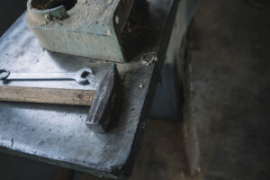
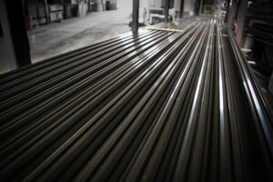
In sheet metal manufacturing, shrinkage refers to the dimensional change that occurs after forming or thermal processes, where a part ends up slightly smaller or shifted from its nominal design dimensions. Unlike plastic molding, shrinkage in sheet metal is not uniform across the entire part. It is typically localized around bends, formed features, and heat-affected zones.
Designers often first notice shrinkage when parts that were dimensionally correct in flat patterns no longer align after bending, or when holes and slots shift slightly from their intended positions. These changes are usually small in absolute terms, but when multiple bends and features are involved, the cumulative effect can lead to visible misalignment at the assembly level.
It’s important to distinguish that shrinkage in sheet metal is not a single, predictable percentage applied to a whole part. Instead, it is the result of material flow during bending, elastic recovery after forming, and thermal contraction after cutting or welding. Each of these mechanisms contributes differently to how and where dimensional change shows up.
In practical terms, shrinkage becomes a design concern when:
- Flange lengths are fit-critical
- Holes must align across bent parts
- Assemblies depend on tight tolerances near bends
- Parts undergo heat input from laser cutting or welding
At Manufyn, shrinkage is treated as a localized, process-dependent behavior that must be accounted for during DFM. Flat patterns, feature placement, and tolerance strategy are reviewed with an understanding of how material will actually move and recover in production.
Seeing small dimensional shifts after bending or welding?
Talk to Manufyn about shrinkage-aware sheet metal design.
Sheet Metal Shrinkage Rate: What Designers Mean by “Rate”
When engineers search for “sheet metal shrinkage rate,” they are usually looking for a simple percentage they can apply during design to compensate for dimensional change. In practice, sheet metal does not shrink in a single uniform rate the way plastics do after molding. Instead, “shrinkage rate” in sheet metal refers to the typical range of dimensional change observed after forming and thermal processing.
This dimensional change is not evenly distributed. It tends to concentrate:
- Near bend lines, where material is plastically deformed
- Around features close to bends, where material flow is constrained
- In heat-affected zones, where localized thermal contraction occurs
As a result, shrinkage rate in sheet metal is best understood as a localized behavior, not a global scale factor. Designers who apply a blanket shrinkage percentage across the entire flat pattern often overcompensate in some regions and undercompensate in others, leading to parts that are still out of tolerance after forming.
In production, what engineers typically observe as “shrinkage rate” is the net dimensional change between the intended formed dimension and the actual measured dimension after bending and cooling. This change is influenced by:
- Material type and temper
- Sheet thickness
- Bend radius and severity
- Amount of heat input (laser cutting, welding)
- Tooling condition and forming method
For this reason, shrinkage rate is better treated as a range of expected dimensional drift rather than a fixed correction factor. In the next section, we’ll look at typical shrinkage rate ranges observed for common sheet metal materials to give designers a realistic starting point.
If you’re applying a single shrinkage % to every part, you’re likely compensating in the wrong places.
Talk to Manufyn about using localized shrinkage behavior instead of blanket corrections.
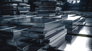
Typical Shrinkage Rates by Material (Practical Reference)
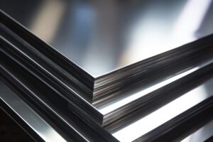
Unlike plastics, sheet metal does not have a single, standardized shrinkage percentage. However, manufacturers do observe repeatable ranges of dimensional change after forming and cooling for common materials. These ranges reflect the combined effects of plastic deformation at bends, elastic recovery, and thermal contraction from processes like laser cutting and welding.
The values below represent typical net dimensional change observed in production across bent features and heat-affected regions. They are best used as early design reference ranges, not exact compensation factors.
Typical Dimensional Shrinkage Observed After Forming & Cooling
| Material | Common Thickness Range | Typical Observed Shrinkage Range* | What This Means in Practice |
|---|---|---|---|
| Mild steel | 1–3 mm | ~0.1% – 0.3% | Small but accumulative across multiple bends |
| Stainless steel | 1–3 mm | ~0.2% – 0.5% | Higher residual stress, more springback interaction |
| Aluminum | 1–3 mm | ~0.3% – 0.8% | More sensitive to heat input and bend severity |
| Copper / Brass | 1–3 mm | ~0.1% – 0.4% | Generally ductile, localized distortion near bends |
| Thicker gauges | 4–6 mm | Can exceed 1% locally near bends | Local shrinkage dominates, global change varies |
Shrinkage here refers to net dimensional change measured between nominal formed dimensions and actual part dimensions after bending and cooling. Localized distortion near bends can exceed these ranges even when overall part length change appears small.
How to Read This Table (Without Misusing It)
These ranges are not meant to be applied as a blanket scale factor to your flat patterns. Instead, they indicate the order of magnitude of dimensional drift you should expect in real forming conditions. For example, aluminum parts with multiple tight bends and laser-cut features are more likely to show noticeable dimensional change than mild steel parts with gentle bends.
Designs that operate near tolerance limits should assume they will experience shrinkage at the upper end of these ranges, especially when:
- Bend radii are tight
- Heat input is high (laser cutting, welding)
- Material temper varies between batches
- Tooling is worn or changed
Why Shrinkage Rate Varies Even Within the Same Material
Even within a single material category, shrinkage behavior varies with:
- Bend severity (tight vs generous radii)
- Feature proximity to bends
- Part geometry (long flat spans vs compact folded parts)
- Process sequence (cut-then-bend vs bend-then-weld)
This is why shrinkage is best managed through design strategies and validation workflows, not by applying a single numeric correction.
If your aluminum or stainless parts show inconsistent dimensional drift, shrinkage variability is likely the underlying cause.
Talk to Manufyn about designing sheet metal parts that tolerate shrinkage in real production.
What Causes Shrinkage in Sheet Metal?
Shrinkage in sheet metal is not caused by a single mechanism. It’s the combined result of how metal deforms during forming and how it responds to heat and stress relief during processing. Understanding these causes helps designers predict where dimensional change is most likely to show up.
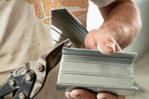
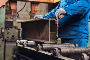
Material Flow During Bending
When a sheet is bent, the material on the outside of the bend stretches while the inside compresses. This plastic deformation redistributes material around the bend line. As a result, the effective length of flanges and the position of nearby features can change slightly from nominal values. The tighter the bend and the thicker the material, the more pronounced this localized shrinkage effect becomes.
Elastic Recovery After Forming
After the forming load is removed, the material partially recovers elastically. This recovery changes bend angles and slightly shifts feature positions relative to the design intent. While elastic recovery is often discussed as springback, it also contributes to net dimensional change that designers experience as “shrinkage” when parts cool and relax into their final shape.
Thermal Contraction From Heat Input
Processes such as laser cutting, plasma cutting, and welding introduce localized heat into the sheet. As the metal cools, it contracts. This thermal contraction can pull features inward, especially around welded seams or heavily cut regions. In thin sheet metal, even small heat-affected zones can create measurable dimensional change.
Residual Stress Release
Forming and cutting introduce residual stresses into the sheet. Over time, or during subsequent operations, these stresses relax. This relaxation can cause subtle dimensional drift, especially in parts with multiple bends or asymmetric geometry. What appears dimensionally stable immediately after forming may change slightly after stress redistribution.
If dimensional drift shows up after cutting, bending, or welding—even when flat patterns were correct—the root cause is usually one of these shrinkage mechanisms.
Talk to Manufyn about identifying shrinkage drivers in your sheet metal process.
Shrinkage vs Springback
Shrinkage and springback are often used interchangeably in conversations about sheet metal dimensional change, but they are not the same phenomenon. Mixing them up leads to the wrong corrective actions in design.
What Shrinkage Is
Shrinkage refers to the net dimensional change a part exhibits after forming and cooling. It shows up as parts ending up slightly smaller or features shifting from their nominal positions. Shrinkage is influenced by plastic deformation, thermal contraction, and residual stress relaxation. It tends to be localized, with the largest effects near bends and heat-affected zones.
What Springback Is
Springback is the elastic recovery of material after a bending force is removed. It primarily affects bend angle rather than overall part size. A part that springs back will open up slightly after bending, resulting in an angle that is larger than intended. Springback does not directly describe length change, but it alters geometry in ways that can indirectly affect fit.
Why Designers Confuse the Two
Both shrinkage and springback result in parts that do not match CAD exactly, and both are influenced by material type, thickness, and bend severity. However, springback is about angle recovery, while shrinkage is about dimensional change along the part. Correcting one does not automatically fix the other.
Why This Distinction Matters in Design
If you compensate for shrinkage when the real issue is springback, you may change flat pattern lengths when what you actually need is angle compensation or tooling adjustment. Conversely, if you adjust bend angles when the problem is localized shrinkage near bends or welds, feature alignment issues will persist.
If parts look the right size but the angles are off, you’re likely dealing with springback. If the angles look right but features don’t line up, shrinkage is usually the culprit.
Talk to Manufyn about diagnosing whether shrinkage or springback is driving your dimensional issues.
How to Estimate Shrinkage Rate During Design
Designers often ask for a formula to “calculate shrinkage rate” so they can compensate for it directly in CAD. In sheet metal, shrinkage can be estimated, but it cannot be predicted with high precision across all geometries and processes. The goal during design is to understand order of magnitude and risk, not to chase exact numeric corrections.
What You Can Estimate Reliably
You can reasonably anticipate higher shrinkage risk when:
- Material is aluminum or stainless steel rather than mild steel
- Bend radii are tight and bend angles are large
- Parts have multiple bends clustered in one region
- Heat input from laser cutting or welding is significant
Designs that combine these factors are more likely to show dimensional drift after forming and cooling.
What You Can’t Predict Accurately
Shrinkage rate varies with:
- Actual tooling geometry and wear
- Material batch properties
- Sequence of operations (cut–bend–weld vs bend–weld)
- Operator setup and forming method
These variables change between suppliers and even between production runs, which is why fixed shrinkage percentages rarely hold up in real production.
How to Use Early Data to Refine Estimates
The most reliable way to estimate shrinkage for a given design is to measure it on first-article parts formed under production-like conditions. By comparing nominal design dimensions with actual formed dimensions, you can characterize typical drift for that material–geometry–process combination and adjust tolerances or design features accordingly.
A Practical Design Approach
Instead of trying to “correct” flat patterns with a global shrinkage factor, design for shrinkage tolerance:
- Place datums away from high-shrinkage zones
- Avoid chaining critical dimensions across multiple bends
- Allow adjustability in assemblies where small shifts are unavoidable
If you’re trying to bake a single shrinkage rate into CAD, you’re solving the wrong problem.
Talk to Manufyn about shrinkage-aware design strategies instead of blanket compensation.
Shrinkage in Prototypes vs Production
Shrinkage-related dimensional drift often goes unnoticed in prototypes and then becomes a recurring issue once parts move into production. This isn’t because shrinkage suddenly appears—it’s because the conditions that reveal it only exist at scale.
Why Prototypes Hide Shrinkage Effects
Prototype parts are usually produced in small quantities with careful setup and close operator attention. Tooling is fresh, material batches are consistent, and minor dimensional shifts are often corrected manually during forming. These factors mask the true extent of shrinkage-related drift.
What Changes at Production Scale
In production, variability becomes unavoidable. Material properties vary from batch to batch, tooling wears over time, and cycle times increase. Heat input from cutting and welding becomes more consistent—and thus more impactful—across large runs. Shrinkage that was negligible in prototypes becomes repeatable and noticeable in production.
The Supplier Change Effect
When production is moved to a different supplier or split across multiple vendors, tooling geometry and process parameters change. Shrinkage behavior that was acceptable in one setup may shift in another, leading to parts that no longer fit assemblies without rework.
Designing for Scale From the Start
Designs that tolerate shrinkage in production build in margin. This includes avoiding tight tolerance chains across multiple bends, placing critical features away from high-shrinkage zones, and validating fit using production-like forming conditions rather than one-off prototype setups.
If parts fit in prototypes but drift in production, shrinkage variability is usually the missing design consideration.
Talk to Manufyn about derisking shrinkage for production scale-up.
Common Mistakes When Accounting for Shrinkage
Shrinkage problems rarely come from complex geometry. They usually come from a few recurring design habits that seem harmless in CAD but create real dimensional drift in production.
Treating Shrinkage as a Uniform Percentage
Applying a single shrinkage rate to an entire flat pattern assumes that every region of the part shrinks equally. In reality, shrinkage is localized around bends and heat-affected zones. This leads to overcompensation in some areas and undercompensation in others, resulting in parts that are still out of tolerance after forming.
Ignoring Heat Input During Secondary Operations
Designers often account for forming but overlook the dimensional impact of laser cutting, welding, or other thermal processes. Heat input causes localized contraction during cooling, which can pull features out of position, especially near seams or heavily cut regions.
Over-Constraining Dimensions Near Bends
Placing tight tolerance chains across multiple bends magnifies the impact of shrinkage. Even small dimensional changes at each bend accumulate, making assemblies sensitive to minor process variation. This is a common cause of “everything is within tolerance, but it still doesn’t fit” scenarios.
Blindly Trusting CAD Unfolds
CAD tools do not model localized shrinkage behavior. Designers who rely solely on software unfold without validating real forming behavior often discover dimensional drift only after parts reach assembly. The CAD model may be dimensionally consistent, but the real part follows material physics, not software assumptions.
Locking Designs After Prototyping
Flat patterns and tolerances are sometimes frozen after prototypes fit. Without validating shrinkage behavior under production conditions, small prototype-level adjustments become chronic sources of misfit at scale.
If the same dimensional issues keep showing up across projects, one of these habits is likely baked into your design process.
Talk to Manufyn about auditing shrinkage assumptions before production.
How to Design Sheet Metal Parts That Tolerate Shrinkage
Shrinkage can’t be eliminated, but its impact on fit and function can be designed around. Parts that assemble smoothly in production are usually the result of shrinkage-aware design choices, not tighter formulas.
Place Critical Features Away From High-Shrinkage Zones
Bends and heat-affected areas experience the most dimensional change. Placing fit-critical holes, slots, or mating edges directly adjacent to these regions makes assemblies sensitive to small shrinkage variations. Shifting these features slightly away from bends improves positional stability after forming.
Avoid Long Tolerance Chains Across Multiple Bends
When critical dimensions span several bends, each bend introduces small dimensional variation. These small shifts accumulate and show up as noticeable misalignment at the assembly level. Breaking long tolerance chains into shorter, locally-referenced dimensions reduces sensitivity to shrinkage.
Choose Datums That Reflect Formed Geometry
Referencing dimensions from flat pattern edges that later move during forming increases error. Where possible, select datums on features that remain stable after forming. This makes post-forming measurement and quality control more meaningful.
Build Adjustability Into Assemblies
Slots instead of fixed holes, floating fasteners, and compliant interfaces give assemblies room to absorb small dimensional shifts caused by shrinkage. This design flexibility often costs little in terms of packaging but pays off in reduced rework and easier assembly.
Accept Small Geometry Changes to Improve Stability
Slightly increasing bend radii, relaxing cosmetic constraints near bends, or redistributing stiffening features can significantly reduce localized shrinkage effects. These small design concessions often improve yield without affecting product performance.
How Manufyn Accounts for Shrinkage Rate in DFM
At Manufyn, shrinkage is treated as a process behavior, not a theoretical percentage. During DFM, designs are reviewed with an understanding of how different materials, forming methods, and heat inputs actually behave in production. The goal is to ensure that dimensional drift caused by shrinkage does not turn into fit issues at scale.
Process-Aware Shrinkage Review
Manufyn evaluates where shrinkage is most likely to occur based on part geometry and process sequence. Bends, clustered features, and heat-affected zones are flagged as higher-risk regions. This allows designers to adjust feature placement or tolerances before designs are locked for tooling.
Material-Specific Behavior Validation
Different materials exhibit different shrinkage tendencies. Aluminum parts that undergo both bending and welding, for example, are reviewed more conservatively than mild steel parts formed without significant heat input. This material-specific lens helps prevent overconfidence in designs that are near tolerance limits.
Flat Pattern & Fit Alignment
Shrinkage behavior is considered alongside flat pattern assumptions. Where necessary, flat pattern parameters and tolerance strategies are adjusted to reduce the impact of localized dimensional change after forming and cooling. The emphasis is on preserving assembly fit rather than chasing nominal CAD dimensions.
Production-Scale Readiness
Designs that operate close to shrinkage-sensitive limits are flagged as higher risk for production scale. Manufyn recommends design adjustments that improve robustness across material batches, tooling setups, and suppliers, reducing the likelihood of dimensional drift appearing months after launch.
If dimensional drift shows up only after production ramps, shrinkage behavior likely wasn’t validated early enough.
Talk to Manufyn about incorporating shrinkage considerations into DFM before release.
Shrinkage-Aware Design Checklist (Production-Ready)
Use this checklist to review sheet metal designs for shrinkage sensitivity before releasing them to manufacturing.
Geometry & Feature Placement
- Are fit-critical features placed away from bends and heat-affected zones?
- Are long tolerance chains across multiple bends avoided where possible?
Material & Process
- Has the shrinkage tendency of the chosen material been considered?
- Will the part undergo heat input (laser cutting, welding) that could introduce localized contraction?
Tolerances & Datums
- Are tolerances placed on features that remain stable after forming?
- Are datums chosen on formed geometry rather than flat pattern edges that move during bending?
Assembly Robustness
- Does the assembly include adjustability (slots, floating fasteners) to absorb small dimensional shifts?
- Are near-limit designs flagged for additional validation under production-like conditions?
Seeing multiple red flags in this checklist?
Talk to Manufyn about a DFM review to make your sheet metal designs robust to shrinkage.
Final Conversion: Stop Chasing Dimensional Drift
Shrinkage is a reality of sheet metal forming and thermal processing. Designs that assume perfectly stable dimensions after bending and cooling often pass early checks but struggle in production with misalignment, rework, and delayed assemblies.
By treating shrinkage as a localized, process-dependent behavior—and designing parts to tolerate it—teams can avoid late-stage design changes, reduce scrap, and maintain fit as volumes scale and suppliers change. The most robust designs are not those that try to “correct” shrinkage numerically, but those that anticipate where shrinkage will occur and limit its impact on fit-critical features.
Manufyn supports shrinkage-aware sheet metal design through DFM workflows that align material behavior, forming processes, and assembly requirements—so parts fit reliably from first article through full-scale production.
Ready to design sheet metal parts that stay in tolerance at scale?
Talk to Manufyn about shrinkage-aware DFM.
FAQs: Sheet Metal Shrinkage Rate
What is shrinkage rate in sheet metal?
Shrinkage rate in sheet metal refers to the typical range of dimensional change observed after forming and cooling, not a single fixed percentage. It varies by material, thickness, bend severity, heat input, and tooling. Shrinkage is usually localized around bends and heat-affected zones.
How much does aluminum shrink when bent?
Aluminum typically shows higher dimensional drift than mild steel due to its sensitivity to heat and forming strain. In production, designers often observe localized dimensional change in the range of ~0.3%–0.8% near bends and heat-affected regions, depending on thickness and bend severity.
Is shrinkage predictable in sheet metal?
Shrinkage is partially predictable in terms of risk and magnitude (order of magnitude), but not precisely predictable as a single compensation factor. Tooling geometry, material batch variation, and process sequence all influence how much dimensional change occurs.
How do I compensate for shrinkage in flat patterns?
Rather than applying a global shrinkage factor, compensate by designing for tolerance: place fit-critical features away from bends, avoid long tolerance chains across multiple bends, and validate flat patterns using first-article measurements under production-like conditions.
Does welding increase shrinkage?
Yes. Welding introduces localized heat that causes thermal contraction as the material cools. This can pull features inward near weld seams and distort nearby geometry, increasing localized shrinkage effects.
Have a shrinkage question specific to your part or process?
Talk to Manufyn about shrinkage-aware DFM for sheet metal parts.