
Ultrasonic Welding Services for High Precision Plastic Assembly
Manufyn provides advanced Ultrasonic Welding Services for engineering thermoplastics including ABS, Nylon, Polycarbonate, Polypropylene (PP), PEEK, Acetal (POM), PET and PBT. We help OEMs, Tier 1 suppliers and product innovators manufacture durable plastic assemblies for demanding industrial applications.
From Injection Molding and tooling to ultrasonic plastic welding, inspection and global logistics, Manufyn delivers complete manufacturing solutions from prototype development to high volume production.
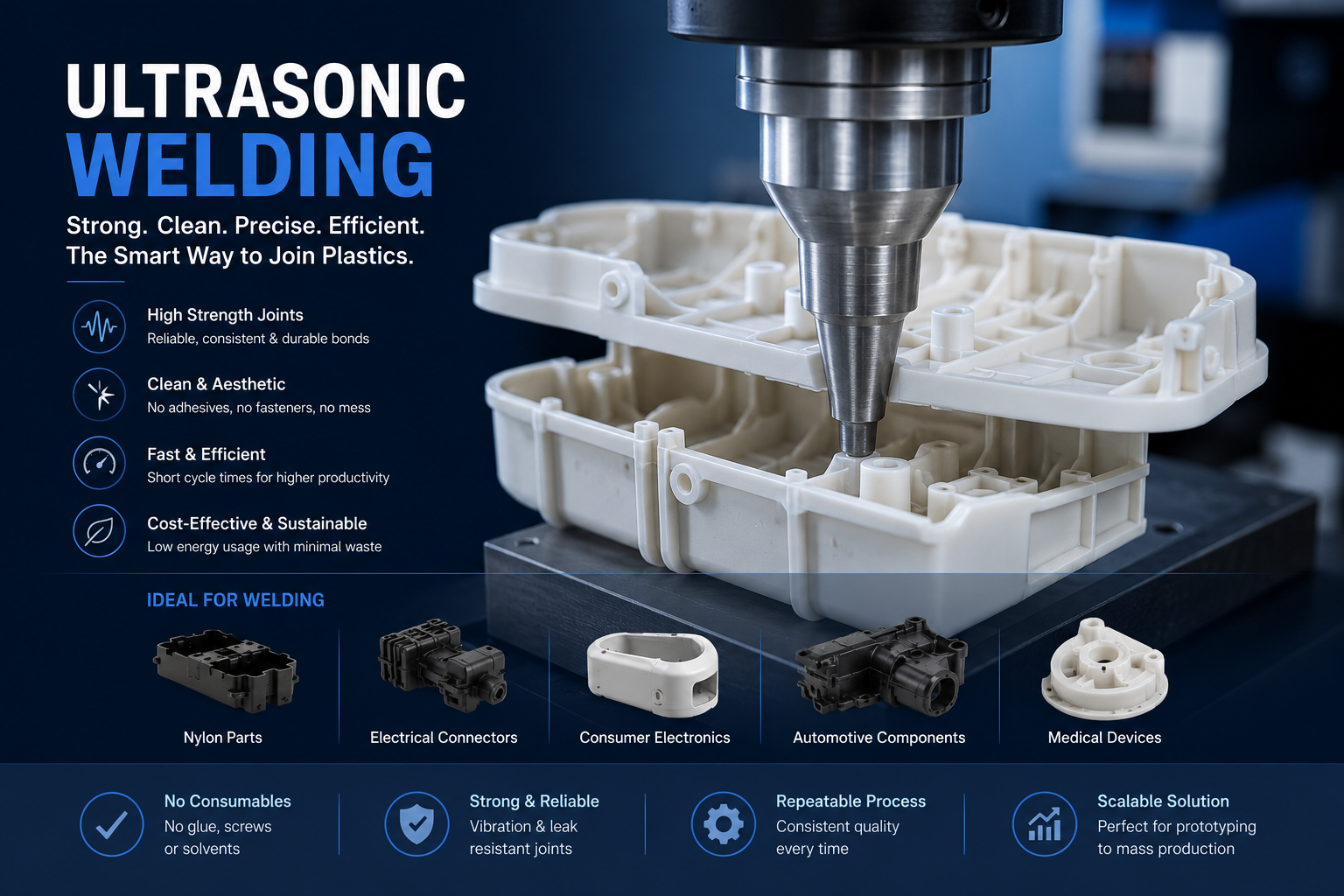
Why Global Manufacturers Choose Manufyn
From prototype development to high volume production, Manufyn combines engineering expertise, vetted manufacturing partners and stringent quality control to deliver precision plastic assemblies for customers worldwide.
50+
Manufacturing Partners
Carefully selected manufacturing partners across India for precision machining, injection molding, ultrasonic welding and secondary operations.
20+
Engineering Materials
Experience welding ABS, Nylon, Polycarbonate, PP, PEEK, POM, PET, PBT and many other engineering thermoplastics.
100%
Quality Inspection
Every production batch undergoes dimensional and visual inspection before shipment to ensure consistent weld quality.
Global
Export Support
Supporting OEMs and product companies across North America, Europe and the Middle East with reliable manufacturing and logistics.
What is Ultrasonic Welding?
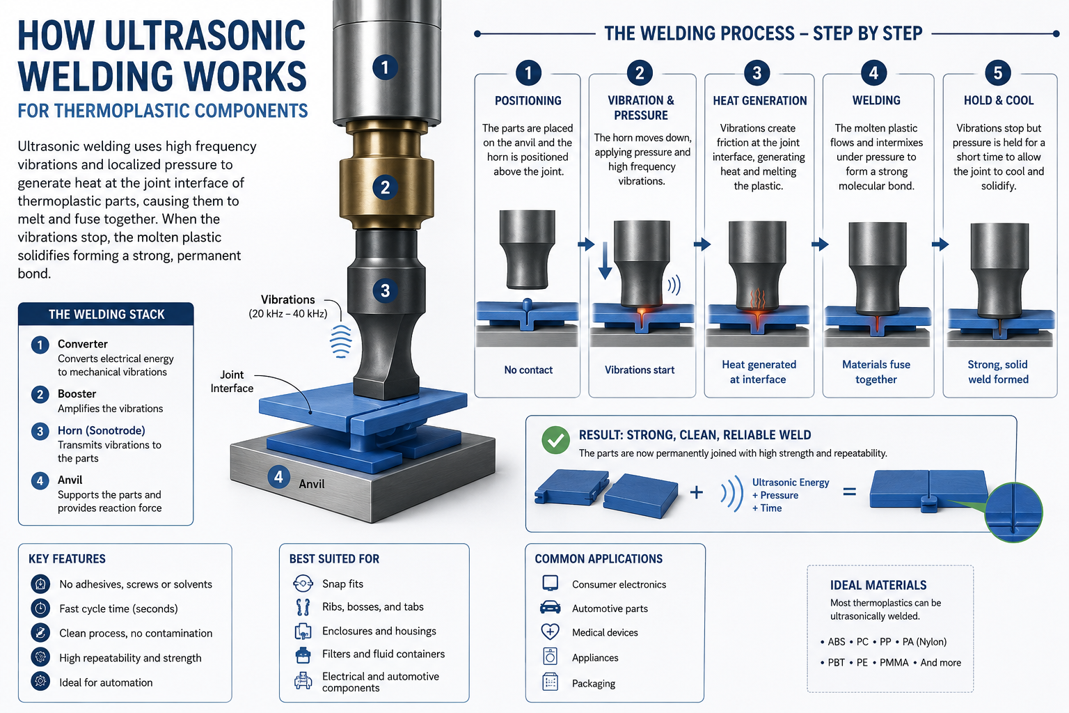
Ultrasonic welding is a high speed manufacturing process used to permanently join thermoplastic components using high frequency mechanical vibrations. Unlike adhesives, screws or solvents, ultrasonic welding creates a strong molecular bond in just a few seconds, making it ideal for high volume manufacturing.
The process converts electrical energy into high frequency mechanical vibrations through an ultrasonic generator, converter, booster and welding horn. When these vibrations are applied under controlled pressure, frictional heat is generated at the joint interface. This softens the plastic surfaces and allows them to fuse together without damaging the surrounding material.
Ultrasonic welding is widely used for manufacturing automotive components, medical devices, electrical housings, consumer products, industrial equipment and precision engineering assemblies because it delivers repeatable weld quality, excellent dimensional accuracy and fast production cycles.
Why Manufacturers Prefer Ultrasonic Welding
The process eliminates adhesives, reduces assembly time, minimizes production costs and produces clean, aesthetically pleasing joints with excellent mechanical strength. It is one of the most reliable plastic joining technologies for engineering thermoplastics.
Why Choose Ultrasonic Welding?
Ultrasonic welding is one of the most efficient methods for joining thermoplastic components. It provides consistent weld quality, short cycle times and excellent repeatability without the need for adhesives or fasteners.
Fast Cycle Time
Complete welds in just a few seconds, making ultrasonic welding ideal for high volume manufacturing and automated production lines.
Strong Molecular Bond
High frequency vibration creates a permanent bond between thermoplastic parts, resulting in durable, leak-resistant assemblies.
No Adhesives Required
The process eliminates glues, solvents and mechanical fasteners, reducing assembly costs while improving product appearance.
Precision Engineering
Excellent control over weld parameters ensures consistent quality for medical devices, electronics and precision industrial components.
Automation Ready
Easily integrates with robotic systems and automated production cells for repeatable, high-speed manufacturing.
Reliable Quality
Produces clean, aesthetically pleasing welds with minimal flash, ensuring consistent performance across production batches.
Engineering Advantages of Ultrasonic Welding
Ultrasonic welding is widely adopted across the automotive, medical, electrical and consumer product industries because it produces clean, repeatable and durable plastic joints without additional consumables. The process is ideal for engineering thermoplastics requiring high dimensional accuracy and short production cycles.
Short Production Cycles
Typical weld cycles range from less than one second to a few seconds, improving manufacturing throughput.
Leak Resistant Joints
Suitable for fluid reservoirs, filters, medical devices and sealed electronic housings.
Lower Manufacturing Cost
No adhesives, curing ovens or mechanical fasteners are required, reducing assembly costs.
Automation Compatible
Integrates easily with robotic handling systems and automated production lines.
Common Applications
Automotive Components
Sensor housings, lighting assemblies, reservoirs, fluid tanks, clips and interior trim components.
Medical Devices
Diagnostic cartridges, fluid management devices, filters and disposable medical products.
Electrical & Electronics
Switches, connectors, battery housings, electrical enclosures and cable management components.
Related Manufacturing Services
Need Precision Ultrasonic Welding for Your Project?
Whether you need prototype quantities or high volume production, our engineering team can recommend the optimal material, joint design and manufacturing process for your application.
Request a Manufacturing QuoteHow Ultrasonic Welding Works
Ultrasonic welding joins thermoplastic components by converting electrical energy into high-frequency mechanical vibrations. Under controlled pressure, these vibrations generate localized frictional heat at the joint interface, allowing the plastic to soften and fuse into a permanent bond without adhesives or mechanical fasteners.
Electrical Power
The ultrasonic generator converts standard electrical power into a controlled high-frequency electrical signal, typically operating at 20 kHz, 30 kHz or 40 kHz depending on the application.
Converter
The converter transforms the electrical signal into high-frequency mechanical vibrations using piezoelectric ceramic elements with exceptional precision and repeatability.
Booster
The booster modifies the vibration amplitude to suit the material, joint geometry and production requirements while transmitting energy efficiently to the welding horn.
Ultrasonic Horn
The horn, also called the sonotrode, transfers ultrasonic vibrations directly into the plastic components while maintaining uniform pressure throughout the weld cycle.
Frictional Heat
The concentrated vibration generates heat at the joint interface, softening only the contact surfaces and creating a molecular bond without affecting the surrounding material.
Permanent Weld
After the vibrations stop, the plastic cools under pressure to form a strong, repeatable and aesthetically clean weld suitable for demanding industrial applications.
Key Ultrasonic Welding Parameters
Achieving a strong and repeatable ultrasonic weld depends on selecting the correct process parameters. Frequency, vibration amplitude and welding pressure are the primary variables that determine weld strength, appearance and production consistency.
Frequency
Ultrasonic welding systems typically operate at 15 kHz, 20 kHz, 30 kHz or 40 kHz. Lower frequencies deliver higher energy for larger components, while higher frequencies provide precise control for smaller or delicate plastic parts.
- 15–20 kHz for large engineering components
- 20 kHz is the most common industrial frequency
- 30–40 kHz for medical and electronic assemblies
- Higher frequency reduces vibration marks
Amplitude
Amplitude represents the distance travelled by the ultrasonic horn during vibration. It directly affects heat generation and weld strength.
- Higher amplitude increases welding energy
- Lower amplitude improves cosmetic appearance
- Must match material characteristics
- Controlled through booster selection
Welding Pressure
Pressure keeps both plastic components in intimate contact during the weld cycle. Proper pressure ensures efficient energy transfer and uniform joint formation.
- Too little pressure causes weak welds
- Too much pressure reduces vibration efficiency
- Pressure should remain consistent throughout production
- Fixture rigidity significantly affects weld quality
Weld Time & Hold Time
Although frequency, amplitude and pressure generate the weld, weld time and hold time determine the final strength, appearance and dimensional stability of the finished component. Proper optimisation of these parameters ensures repeatable production quality.
Weld Time
Weld time is the duration during which ultrasonic vibrations are applied to the plastic components. During this period, frictional heat softens the joint interface and forms the molecular bond.
- Short weld times may produce weak joints.
- Excessive weld time can cause flash or deformation.
- Typical cycles range from less than one second to several seconds depending on material and part geometry.
- Engineering plastics such as Nylon and Polycarbonate generally require different weld settings than ABS or PP.
Hold Time
Hold time is the period immediately after ultrasonic vibrations stop while pressure continues to be applied. This allows the molten plastic to solidify under controlled conditions and creates a strong, stable joint.
- Improves weld strength.
- Reduces shrinkage and internal stresses.
- Prevents part separation during cooling.
- Provides better dimensional consistency.
Trigger Force & Collapse Distance
In addition to frequency, amplitude, pressure, weld time and hold time, modern ultrasonic welding systems use trigger force and collapse distance to improve process stability and achieve consistent weld quality across production batches.
Trigger Force
Trigger force is the minimum force applied by the ultrasonic horn before the machine begins transmitting ultrasonic energy. This ensures proper contact between the horn and the plastic component before welding starts.
- Ensures consistent weld initiation.
- Prevents premature vibration.
- Improves repeatability across production.
- Protects delicate components from impact loading.
- Reduces variation between successive welds.
Collapse Distance
Collapse distance is the amount of vertical movement of the ultrasonic horn during welding as the plastic material melts and flows. Monitoring collapse distance provides excellent control over weld consistency and joint quality.
- Measures material flow during welding.
- Provides highly repeatable weld quality.
- Compensates for material thickness variation.
- Commonly used in medical and automotive applications.
- Helps verify complete joint formation.
Energy Mode
Modern ultrasonic welding machines can control the welding process using several methods. One of the most reliable methods is Energy Mode, where the welding cycle automatically stops after a predetermined amount of ultrasonic energy has been delivered into the plastic components.
How Energy Mode Works
Instead of stopping after a fixed time, the ultrasonic welder continuously measures the energy delivered to the joint. Once the programmed energy value is reached, the machine automatically stops the ultrasonic vibrations and enters the hold phase. This approach compensates for small variations in material properties, moulding conditions and part dimensions.
Time Mode Control
In Time Mode, ultrasonic vibrations are applied for a fixed duration programmed into the welding machine. Once the preset weld time has elapsed, the ultrasonic energy automatically stops, and the machine enters the hold phase. This is one of the simplest and most widely used control methods for thermoplastic assembly.
Time Mode is particularly effective when moulded parts have consistent dimensions, stable material properties and well-controlled manufacturing processes. Because every welding cycle follows the same programmed duration, it offers straightforward process setup and repeatable production when component variation is minimal.
Simple Programming
Easy to configure, making it ideal for standard production applications and initial process development.
Fast Production
Maintains consistent production speed because every cycle operates with the same weld duration.
Best For
ABS, Polypropylene, Polycarbonate and other moulded components with tight dimensional tolerances.
Limitations
If part dimensions or material properties vary significantly, weld quality may become inconsistent because the machine does not compensate for these changes.
Distance (Collapse) Mode
Distance Mode, often referred to as Collapse Mode, controls the welding process based on the actual movement of the ultrasonic horn. Instead of stopping after a preset time or energy value, the welding cycle ends only after the programmed collapse distance has been achieved.
Because this method measures the physical movement of the welded joint, it provides excellent process repeatability and compensates for small variations in part dimensions, making it one of the preferred control methods for precision plastic assemblies.
Highest Repeatability
Controls the actual material collapse instead of relying only on time or energy.
Excellent Dimensional Control
Ideal where tight dimensional tolerances are required.
Medical & Automotive
Frequently used in regulated industries requiring highly consistent weld quality.
Production Monitoring
Provides excellent traceability because every weld reaches the programmed collapse distance.
Comparison of Ultrasonic Welding Control Modes
| Control Mode | Controlled By | Advantages | Typical Applications |
|---|---|---|---|
| Time Mode | Preset Weld Time | Simple programming and fast setup | General purpose plastic assemblies |
| Energy Mode | Delivered Ultrasonic Energy | Compensates for material variation | Automotive, Electronics, Medical |
| Distance Mode | Collapse Distance | Highest repeatability and dimensional accuracy | Medical Devices, Precision Engineering, Automotive Safety Components |
Selecting the Right Welding Parameters
Achieving a strong and repeatable ultrasonic weld requires selecting the correct machine settings based on the plastic material, component geometry, joint design, wall thickness and production volume. Optimising these parameters helps minimise defects while maximising weld strength and production efficiency.
Material Characteristics
- Amorphous plastics generally weld more easily than semi-crystalline materials.
- Higher melting temperatures require greater ultrasonic energy.
- Moisture absorption can significantly influence weld quality.
- Glass-filled engineering plastics often require higher amplitudes.
- Material compatibility is essential when joining dissimilar plastics.
Component Design
- Joint geometry determines energy concentration.
- Uniform wall thickness improves weld consistency.
- Proper fixture support reduces vibration losses.
- Avoid excessive flash by maintaining dimensional accuracy.
- Energy directors improve initial melting efficiency.
Machine Settings
- Select appropriate frequency for component size.
- Optimise welding pressure for material stiffness.
- Adjust amplitude according to resin properties.
- Use suitable hold time for cooling.
- Validate trigger force before production.
Production Validation
- Perform destructive weld testing.
- Monitor collapse distance during production.
- Record energy consumption for SPC analysis.
- Validate dimensional accuracy after welding.
- Maintain preventive maintenance schedules.
Engineering Best Practice
Instead of optimising a single parameter, experienced manufacturing engineers develop a complete process window by balancing welding pressure, amplitude, frequency, weld time, energy input and hold time. This approach provides higher process capability (Cp and Cpk), lower rejection rates and improved long-term production stability for automotive, medical and electronics manufacturing.
Materials Suitable for Ultrasonic Welding
Not every thermoplastic responds to ultrasonic welding in the same way. Weld quality depends on the material’s molecular structure, melting temperature, stiffness, moisture absorption and energy transmission characteristics. Selecting the correct material and joint design is essential for achieving strong, repeatable welds in high-volume manufacturing.
Amorphous Thermoplastics
Amorphous plastics soften gradually rather than having a sharp melting point. They transmit ultrasonic vibrations efficiently, making them among the easiest engineering plastics to weld.
- Excellent energy transmission
- Fast welding cycles
- Strong cosmetic appearance
- High dimensional stability
- Suitable for precision assemblies
Common materials include ABS, Polycarbonate (PC), Acrylic (PMMA), Polystyrene (PS), SAN and PVC.
Semi Crystalline Thermoplastics
Semi-crystalline plastics have a defined melting temperature and generally require higher ultrasonic energy. Proper joint design and machine parameter optimisation become increasingly important when welding these engineering materials.
- Require higher energy input
- Often need larger energy directors
- Higher welding pressures
- Greater process optimisation
- Excellent mechanical performance after welding
Examples include Nylon (PA6 & PA66), Polypropylene (PP), Polyethylene (HDPE), Acetal (POM) and PEEK.
Engineering Insight
For applications requiring maximum weld consistency, engineers evaluate not only the plastic grade but also filler content, moisture level, moulding quality, wall thickness and joint geometry. Glass-filled engineering plastics, flame-retardant grades and reinforced polymers often require customised welding parameters compared with unfilled materials.
ABS (Acrylonitrile Butadiene Styrene)
ABS is one of the most commonly welded thermoplastics using ultrasonic welding. Being an amorphous plastic, it efficiently transmits ultrasonic vibrations, allowing rapid melting at the joint interface and producing clean, aesthetically pleasing welds with minimal flash.
- Excellent ultrasonic energy transmission
- Very short welding cycle time
- High cosmetic finish
- Strong structural joints
- Suitable for automation
- Ideal for electrical housings
- Excellent dimensional stability
Typical applications include automotive interior parts, electrical enclosures, consumer products, medical housings, battery cases and appliance components.
Polycarbonate (PC)
Polycarbonate provides outstanding weld strength through ultrasonic welding while maintaining its excellent impact resistance and optical clarity. It is widely used in precision engineering applications where dimensional stability and structural integrity are critical.
- Excellent impact strength
- High dimensional accuracy
- Excellent weld consistency
- Suitable for transparent parts
- Medical device compatible
- High temperature resistance
- Outstanding electrical insulation
Polycarbonate is frequently selected for automotive lighting, medical devices, electrical connectors, transparent covers, industrial sensors and electronic assemblies.
Nylon (PA6 & PA66)
Nylon is one of the most widely used engineering thermoplastics in the automotive, electrical and industrial sectors. As a semi-crystalline polymer, Nylon requires higher ultrasonic energy than amorphous plastics such as ABS or Polycarbonate. With the correct joint design, moisture control and optimized welding parameters, ultrasonic welding produces exceptionally strong structural joints.
- Excellent mechanical strength
- High wear and abrasion resistance
- Good fatigue performance
- Suitable for glass-filled grades
- Excellent for load-bearing assemblies
- High temperature capability
- Good chemical resistance
For best results, Nylon components should be properly dried before welding since excessive moisture reduces weld consistency and may introduce porosity within the joint.
Typical applications include automotive under-hood components, electrical connectors, gears, cable management systems, fluid handling components, appliance assemblies and industrial machine parts.
Polypropylene (PP)
Polypropylene is a lightweight semi-crystalline thermoplastic commonly selected for consumer products, medical devices and automotive applications. Although PP can be successfully ultrasonically welded, it requires greater process optimization because of its lower surface energy and narrower processing window.
- Excellent chemical resistance
- Very low density
- Outstanding fatigue resistance
- Good living hinge performance
- Cost effective engineering material
- Excellent moisture resistance
- Suitable for high-volume production
Joint design plays a critical role when welding Polypropylene. Larger energy directors, optimized amplitude and carefully controlled welding pressure generally produce the most reliable results.
Polypropylene is widely used for medical containers, battery housings, fluid reservoirs, food-grade packaging, automotive reservoirs, laboratory equipment and consumer appliances.
Engineering Recommendation
When selecting materials for ultrasonic welding, engineers should consider not only weldability but also long-term mechanical performance, operating temperature, chemical exposure, dimensional tolerances and production volume. Proper material selection, combined with optimized energy directors and validated welding parameters, significantly improves joint strength, reduces rejection rates and enhances production repeatability. At Manufyn, our engineering team supports customers throughout the product development lifecycle, from plastic injection molding and tool design to precision machining, ultrasonic welding, assembly and final quality inspection.
PEEK (Polyether Ether Ketone)
PEEK is one of the world’s highest-performance engineering thermoplastics. It offers exceptional mechanical strength, continuous operating temperatures exceeding 250°C, outstanding chemical resistance and excellent wear properties. Due to its very high melting temperature, ultrasonic welding requires carefully optimized machine settings, precision tooling and well-designed energy directors.
- Exceptional mechanical properties
- Outstanding chemical resistance
- Continuous high-temperature performance
- Medical and aerospace approved grades
- Excellent fatigue resistance
- Low outgassing characteristics
- Premium engineering material
PEEK is commonly used for surgical instruments, aerospace components, semiconductor equipment, oil & gas applications, electrical insulation components and high-performance industrial machinery.
POM (Acetal / Delrin®)
Polyoxymethylene (POM), commonly referred to as Acetal or Delrin®, combines high stiffness with excellent dimensional stability. Ultrasonic welding produces reliable joints when sufficient energy concentration is achieved through proper joint design.
- Excellent dimensional stability
- Very low friction
- High wear resistance
- Excellent fatigue life
- Good machinability
- Low moisture absorption
- Ideal for precision mechanisms
Typical applications include gears, bearings, lock mechanisms, fuel system components, valve assemblies, electrical connectors and precision industrial equipment.
HDPE (High Density Polyethylene)
HDPE provides excellent impact resistance, chemical resistance and low moisture absorption. Due to its semi-crystalline structure, ultrasonic welding requires higher amplitudes and carefully optimized welding parameters to achieve repeatable joints.
- Excellent chemical resistance
- Very good impact strength
- Lightweight material
- Food-grade compatibility
- Moisture resistant
- Economical for high-volume production
HDPE is widely used in tanks, fluid reservoirs, laboratory equipment, medical containers, piping systems and industrial storage products.
PMMA (Acrylic)
PMMA is an amorphous thermoplastic that responds exceptionally well to ultrasonic welding. It enables clean weld lines with excellent optical clarity, making it suitable for transparent components requiring attractive cosmetic finishes.
- Excellent optical clarity
- High surface finish
- Fast welding cycles
- Excellent dimensional stability
- Suitable for transparent assemblies
- Good UV resistance
Common applications include lighting systems, medical diagnostics, transparent covers, display components, laboratory equipment and consumer electronics.
Material Selection Best Practices
Selecting the right engineering plastic involves balancing weldability, mechanical performance, environmental resistance and manufacturing cost. Amorphous materials such as ABS, Polycarbonate and PMMA generally provide the easiest ultrasonic welding, while semi-crystalline materials including Nylon, Polypropylene, HDPE, POM and PEEK require greater process optimization. Combining proper material selection with robust injection molding, precision tool design, optimized ultrasonic welding and comprehensive quality inspection ensures long-term product reliability and consistent production performance.
Ultrasonic Welding Material Comparison
Choosing the correct thermoplastic is one of the most important decisions during product development. The table below compares commonly used engineering plastics based on weldability, manufacturing difficulty, typical industries and engineering recommendations.
| Material | Weldability | Difficulty | Typical Industries | Engineering Recommendation |
|---|---|---|---|---|
| ABS | ★★★★★ Excellent | Easy | Automotive, Consumer Electronics, Electrical | One of the easiest plastics for ultrasonic welding with excellent cosmetic finish. |
| Polycarbonate (PC) | ★★★★★ Excellent | Easy | Medical, Electronics, Lighting | Excellent dimensional stability and structural weld strength. |
| PMMA (Acrylic) | ★★★★★ Excellent | Easy | Lighting, Medical, Displays | Excellent optical appearance with fast welding cycles. |
| Nylon PA6 / PA66 | ★★★★☆ Very Good | Moderate | Automotive, Industrial Machinery | Dry material thoroughly before welding to achieve consistent results. |
| POM (Acetal) | ★★★★☆ Good | Moderate | Precision Components, Gears | Requires optimized joint geometry and proper fixture support. |
| Polypropylene (PP) | ★★★☆☆ Moderate | Moderate | Medical, Packaging, Consumer Goods | Requires larger energy directors and optimized process parameters. |
| HDPE | ★★★☆☆ Moderate | Moderate | Fluid Handling, Containers | Higher amplitudes generally improve weld consistency. |
| PEEK | ★★★☆☆ Challenging | Difficult | Aerospace, Medical, Semiconductor | Requires precision tooling and advanced process optimization. |
| Glass Filled Plastics | ★★★★☆ Good | Moderate | Automotive, Electrical | Often require higher amplitudes because glass fibers absorb vibration energy. |
Material Selection Matters
Material selection should always be evaluated together with joint design, wall thickness, moulding quality, moisture content, fixture design and production volume. Even materials with moderate weldability can consistently achieve excellent weld strength when supported by optimized tooling, validated process parameters and robust quality control. At Manufyn, our engineering team assists customers from plastic injection molding, tool design and precision CNC machining through ultrasonic welding, assembly, inspection and global manufacturing support.
Ultrasonic Weld Joint Designs
The strength of an ultrasonic weld depends not only on machine parameters but also on the joint geometry designed into the plastic component. Proper joint design concentrates ultrasonic energy at the correct location, improves weld consistency, reduces flash generation and increases overall production reliability. Selecting the appropriate joint design during the product development stage significantly improves manufacturing performance and minimizes quality issues in mass production.
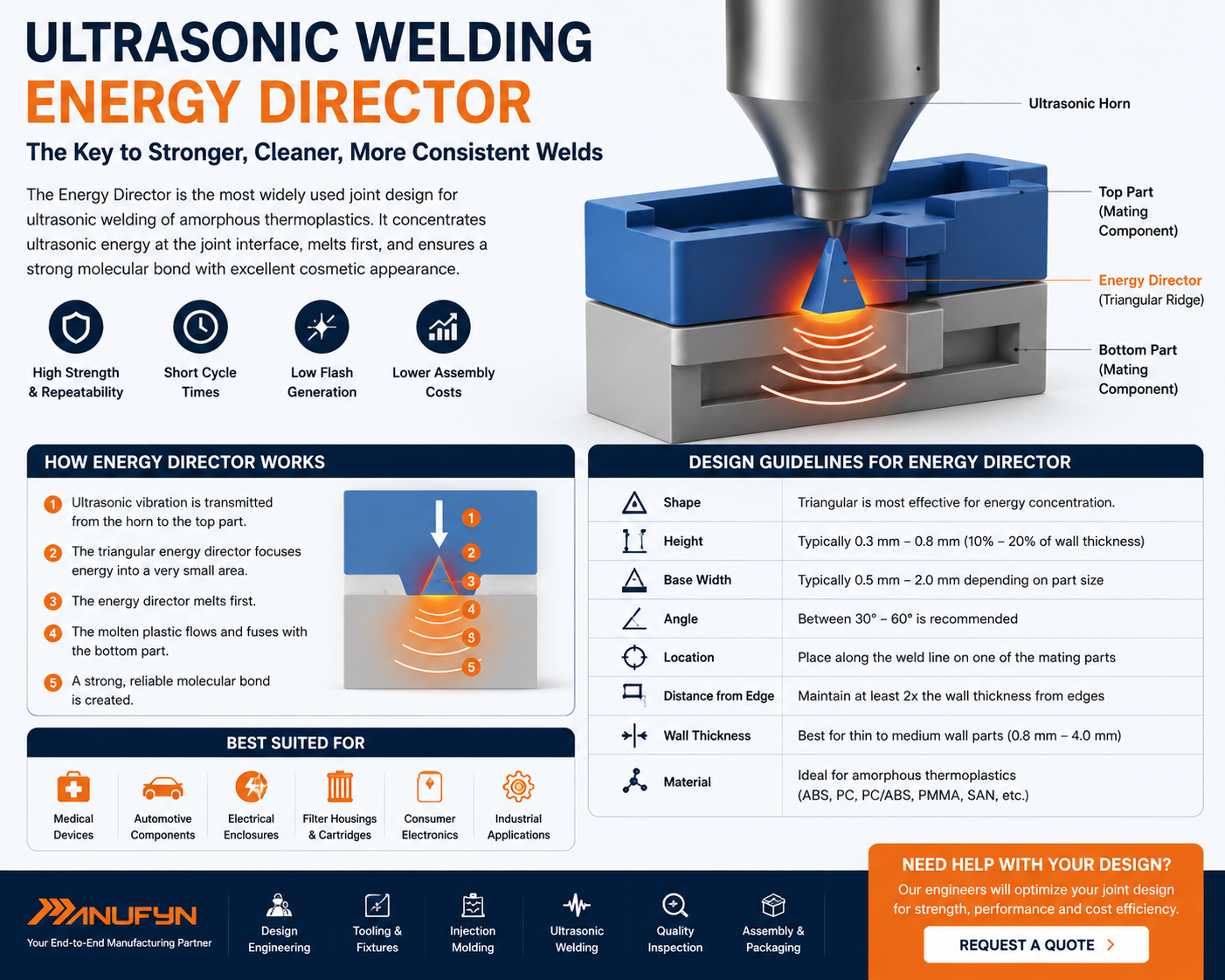
Energy Director
The Energy Director is the most widely used joint design for ultrasonic welding of amorphous thermoplastics. It consists of a small triangular ridge molded into one of the mating components. During welding, this ridge melts first, concentrating the ultrasonic energy into a very small area and creating rapid fusion between the two plastic parts.
- Fastest weld initiation
- Excellent cosmetic appearance
- Low energy consumption
- Very short cycle times
- Ideal for automated production
- Excellent repeatability
- Suitable for high-volume manufacturing
Energy Director joints are commonly used for ABS, Polycarbonate, PMMA and other amorphous engineering plastics where precision and aesthetics are equally important.
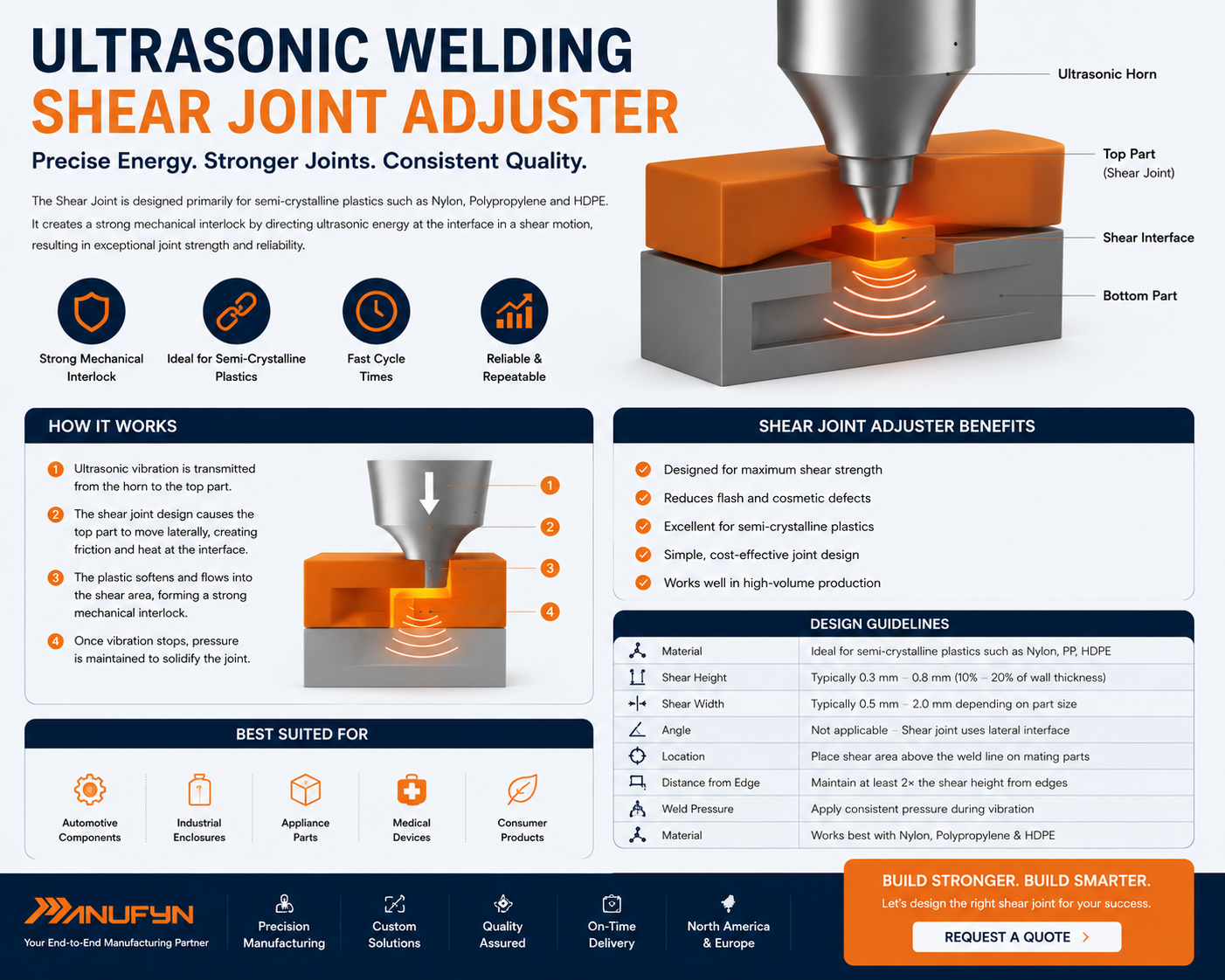
Shear Joint
The Shear Joint is designed primarily for semi-crystalline plastics such as Nylon, Polypropylene and HDPE. Instead of melting a small energy director, the vertical interference between the mating walls generates heat progressively, creating exceptionally strong structural welds and excellent hermetic sealing performance.
- Highest structural strength
- Excellent leak resistance
- Ideal for pressure-tight assemblies
- Preferred for semi-crystalline plastics
- Excellent dimensional accuracy
- Suitable for fluid handling products
- Long-term durability
Shear joints are widely used for automotive reservoirs, medical devices, filtration systems, battery housings, industrial containers and fluid management components requiring leak-proof sealing.
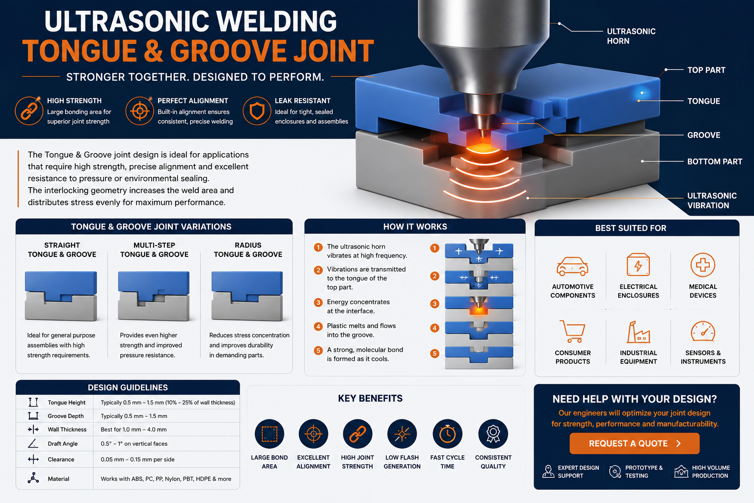
Tongue & Groove Joint
The Tongue & Groove Joint combines precise component alignment with excellent flash containment. A projecting tongue on one component fits accurately into a matching groove on the mating part, allowing molten plastic to remain inside the joint during ultrasonic welding. This design improves aesthetics while producing strong and repeatable welds.
- Excellent component alignment
- Reduces visible flash
- Improves cosmetic appearance
- Suitable for medium to large components
- Provides accurate positioning before welding
- Excellent dimensional repeatability
- Can improve sealing performance
Tongue & Groove joints are commonly used for electronic housings, medical equipment, consumer appliances, electrical enclosures and automotive interior assemblies where appearance is as important as structural strength.
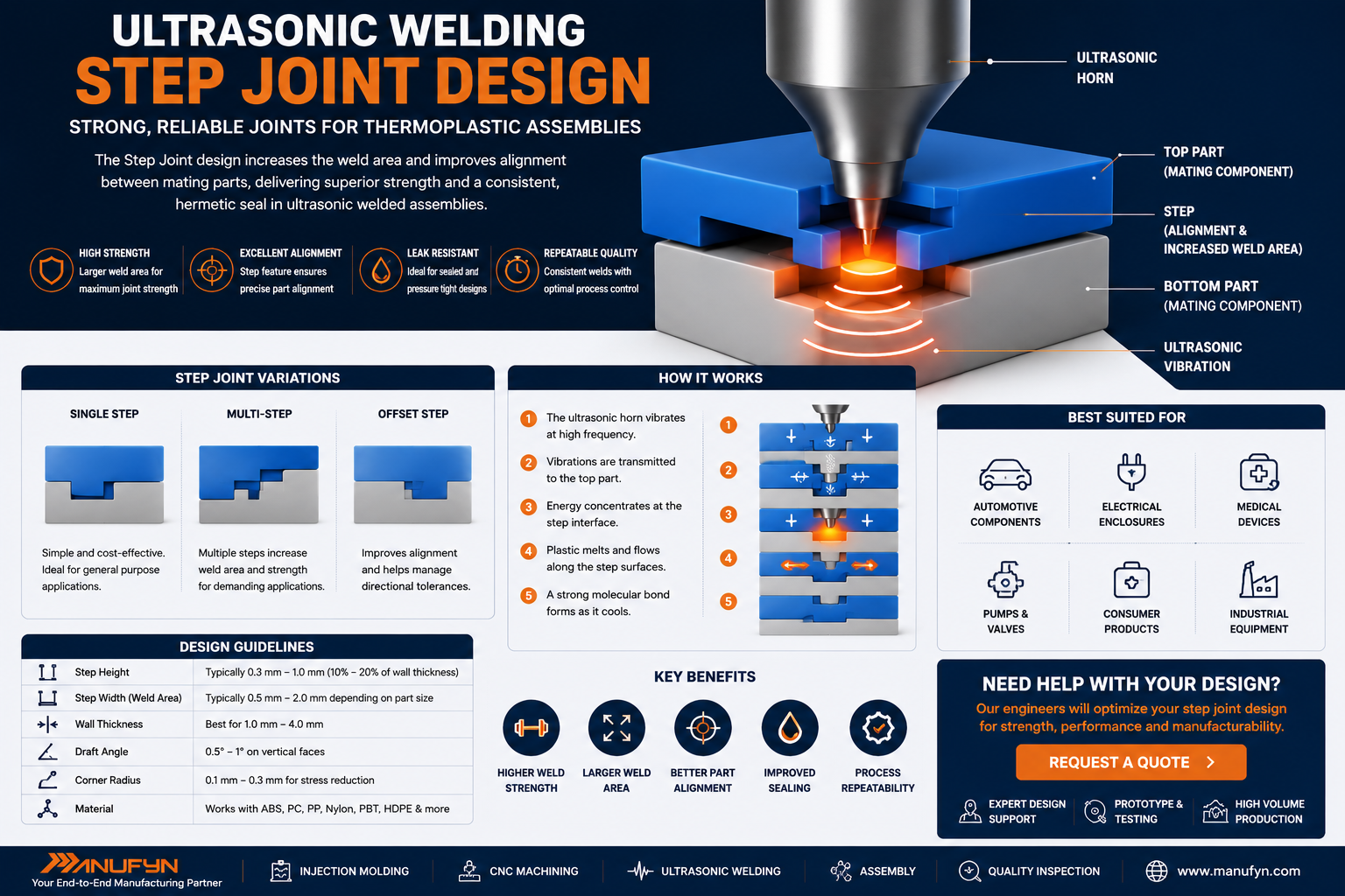
Step Joint
Step Joints incorporate a stepped interface between the two plastic components. This design increases the available welding surface while improving alignment and hiding the weld line from external view. It is especially effective where improved appearance and moderate sealing performance are required.
- Hidden weld line
- Improved product aesthetics
- Better alignment during assembly
- Larger welding surface
- Good dimensional accuracy
- Suitable for consumer products
- Simple tooling design
Typical applications include appliance housings, medical instrument covers, battery enclosures, consumer electronics and industrial control panels.
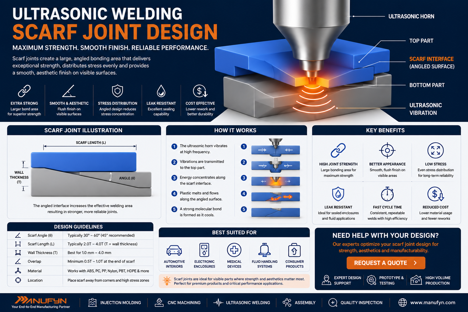
Scarf Joint
A Scarf Joint uses an angled mating surface rather than a flat interface. As ultrasonic energy is applied, the weld progresses gradually along the angled surface, distributing stresses more evenly and reducing the likelihood of stress concentrations. This design is particularly useful for larger plastic components and products subjected to repeated loading.
- Gradual energy distribution
- Reduced stress concentration
- Improved structural integrity
- Suitable for larger assemblies
- Good vibration resistance
- Enhanced fatigue performance
- Consistent weld progression
Scarf joints are frequently used in industrial machinery, automotive systems, electrical equipment, medical housings and engineered plastic products where long service life is required.
Engineering Design Recommendation
The most suitable joint design depends on the material being welded, the required joint strength, sealing requirements, cosmetic expectations and production volume. While Energy Director joints are generally preferred for amorphous plastics such as ABS and Polycarbonate, Shear Joints typically deliver superior performance for semi-crystalline materials including Nylon, Polypropylene and HDPE. Tongue & Groove, Step and Scarf joints provide additional design flexibility where alignment, appearance or structural performance are critical.
During product development, Manufyn’s engineering team evaluates material selection, injection mould design, tolerance stack-up, wall thickness, ultrasonic horn access and fixture design to ensure reliable high-volume manufacturing with minimal rejection rates.
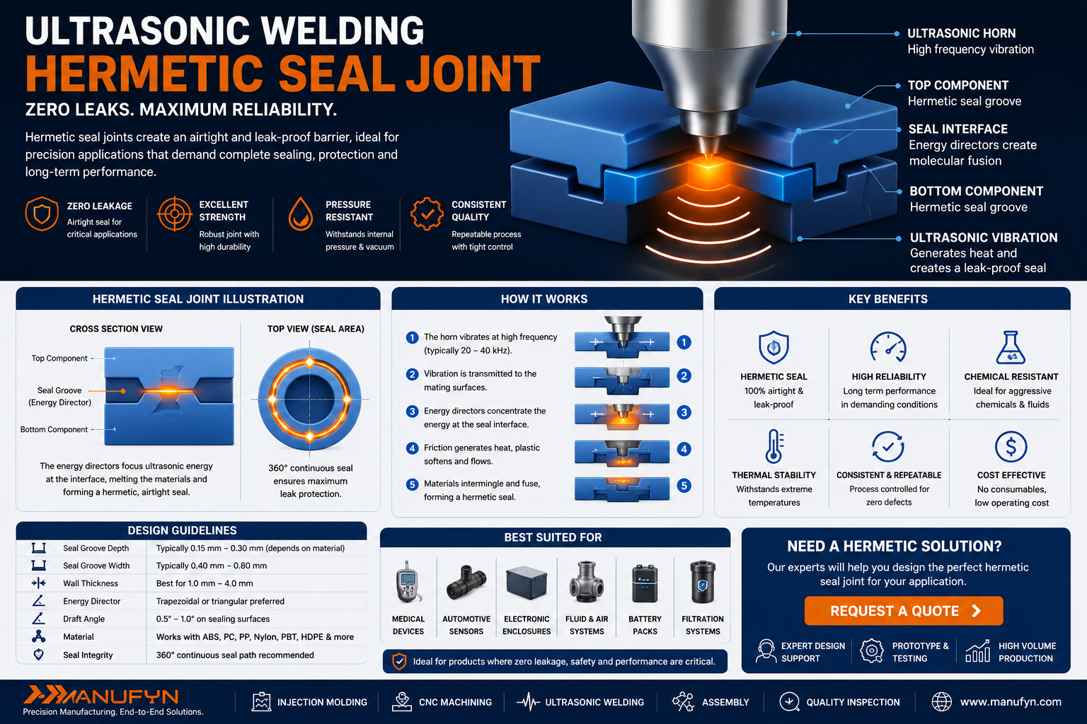
Hermetic Seal Joint
Hermetic seal joints are specifically engineered for applications where airtight or liquid-tight sealing is essential. They are commonly developed using an interference fit combined with precision-controlled ultrasonic energy to create continuous molecular bonding around the complete joint perimeter.
- Excellent leak resistance
- Suitable for pressure vessels
- High structural integrity
- Outstanding environmental sealing
- Ideal for medical and automotive products
- Long service life
- Reliable production repeatability
Typical applications include fluid reservoirs, battery housings, medical cartridges, laboratory equipment, sensors, filtration systems, automotive coolant tanks and electronic enclosures requiring IP-rated sealing.
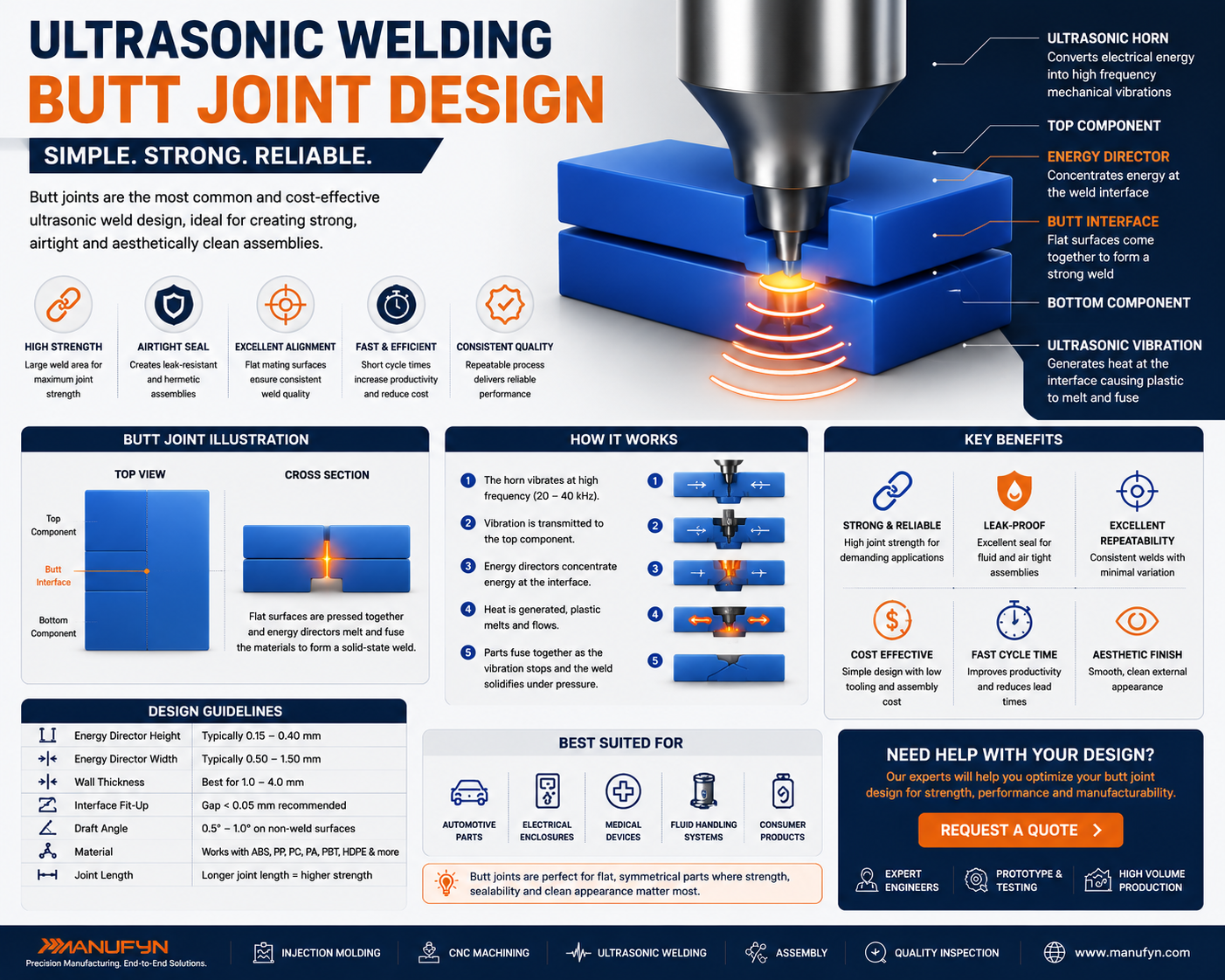
Butt Joint
A Butt Joint joins two flat mating surfaces directly together. Although this is the simplest joint geometry to manufacture, it is generally recommended only for lightly loaded assemblies because ultrasonic energy is distributed over a relatively large surface area, reducing energy concentration.
- Simple tooling
- Low mould complexity
- Economical production
- Fast mould manufacturing
- Suitable for simple products
- Limited structural performance
- Requires accurate part alignment
Typical applications include disposable products, packaging components, consumer products and low-load assemblies where cost is the primary consideration.
| Joint Type | Strength | Appearance | Leak Resistance | Best Materials | Typical Applications |
|---|---|---|---|---|---|
| Energy Director | ★★★★★ | ★★★★★ | ★★★★☆ | ABS, PC, PMMA | Electronics, Consumer Products |
| Shear Joint | ★★★★★ | ★★★★☆ | ★★★★★ | Nylon, PP, HDPE | Automotive, Medical |
| Tongue & Groove | ★★★★☆ | ★★★★★ | ★★★★☆ | ABS, PC | Electrical Enclosures |
| Step Joint | ★★★★☆ | ★★★★★ | ★★★☆☆ | General Engineering Plastics | Consumer Products |
| Scarf Joint | ★★★★★ | ★★★★☆ | ★★★★☆ | Engineering Plastics | Industrial Equipment |
| Hermetic Joint | ★★★★★ | ★★★★☆ | ★★★★★ | Medical & Automotive Plastics | Fluid Systems |
| Butt Joint | ★★★☆☆ | ★★★☆☆ | ★★☆☆☆ | General Purpose Plastics | Packaging |
Common Joint Design Mistakes
- Insufficient energy director height
- Poor wall thickness consistency
- Large unsupported welding surfaces
- Ignoring mould shrinkage
- Incorrect horn contact area
- No fixture support
- Poor venting of trapped air
- Improper tolerance stack-up
Engineering Best Practices
- Design joints during the product development stage
- Select the joint based on material characteristics
- Validate using prototype weld trials
- Perform destructive testing
- Measure collapse distance during validation
- Maintain consistent moulding conditions
- Use SPC for production monitoring
- Review DFM before tooling release
Complete Manufacturing Support from Design to Production
An effective ultrasonic weld begins long before production. It starts with robust product design, proper material selection, precision mould manufacturing and process validation. At Manufyn, we support customers throughout the entire manufacturing lifecycle—from tool design and plastic injection molding to precision CNC machining, 5 Axis CNC machining, quality inspection, product assembly and ultrasonic welding. Our engineering team also provides assistance with design guides, manufacturing resources, case studies, prototype development and production optimisation to help customers reduce costs, improve quality and accelerate product launch.
Ultrasonic Welding Design Guidelines
Successful ultrasonic welding begins during the product design stage rather than on the production floor. Proper part geometry, material selection, joint design and tooling considerations help achieve stronger welds, shorter cycle times and consistent production quality. Following established Design for Manufacturing (DFM) principles also minimizes tooling modifications, improves process capability and reduces manufacturing costs.
1. Maintain Uniform Wall Thickness
Uniform wall thickness ensures that ultrasonic vibrations travel consistently throughout the component. Sudden changes in section thickness can absorb ultrasonic energy, resulting in incomplete welds, excessive flash or cosmetic defects.
- Maintain consistent wall sections wherever possible.
- Avoid abrupt transitions between thick and thin areas.
- Use gradual radii instead of sharp steps.
- Reduce internal stresses during moulding.
- Improve weld repeatability and dimensional stability.
2. Design Proper Energy Directors
Energy directors concentrate ultrasonic energy into a small contact area, initiating rapid melting at the joint interface. Proper dimensions depend on material type, wall thickness and required weld strength.
- Use triangular energy directors for amorphous plastics.
- Match dimensions to wall thickness.
- Maintain consistent geometry around the entire joint.
- Avoid oversized energy directors that generate excessive flash.
- Validate dimensions through prototype welding trials.
3. Ensure Accurate Part Alignment
Proper alignment features prevent component movement during welding and ensure that ultrasonic energy is delivered precisely to the intended joint.
- Use locating bosses and guide features.
- Design self-aligning mating surfaces.
- Reduce assembly variation.
- Prevent horn slippage.
- Improve dimensional repeatability.
4. Design Rigid Support Fixtures
A properly designed fixture supports the component during welding, preventing unwanted movement or vibration that can reduce weld quality. Fixture design is particularly important for complex geometries and thin-wall plastic parts.
- Support the entire welding area.
- Prevent part deformation.
- Maintain consistent horn contact.
- Reduce vibration losses.
- Improve process repeatability.
Advanced Design Considerations for Reliable Ultrasonic Welding
Beyond selecting the appropriate joint geometry, successful ultrasonic welding depends on several critical design factors including rib placement, boss design, draft angles, tolerance control, moisture management and fixture support. Incorporating these recommendations during the product development phase helps improve weld strength, reduce production variation and minimize tooling revisions.
5. Optimize Boss Design
Bosses are frequently used for locating screws, inserts and mating components. If positioned too close to the weld joint, they can absorb ultrasonic energy, resulting in incomplete weld formation or cosmetic defects.
- Maintain adequate clearance between bosses and weld joints.
- Use generous fillet radii at the boss base.
- Avoid excessive boss height.
- Ensure uniform surrounding wall thickness.
- Validate boss strength using prototype testing.
6. Design Ribs Carefully
Structural ribs improve stiffness while minimizing material usage. However, poorly designed ribs can interrupt ultrasonic vibration and create localized stress concentrations that reduce weld quality.
- Keep rib thickness between 50% and 60% of the nominal wall.
- Avoid placing ribs directly beneath the weld interface.
- Maintain smooth transitions with generous radii.
- Use symmetrical rib layouts where possible.
- Reduce sink marks and internal stresses.
7. Apply Appropriate Draft Angles
Draft angles simplify part ejection during injection molding while preserving dimensional accuracy. Adequate draft also minimizes damage to critical welding features during mould release.
- Provide draft on all vertical walls.
- Avoid excessive draft on precision locating features.
- Protect energy directors during mould ejection.
- Maintain dimensional consistency.
- Review draft during DFM analysis.
8. Use Proper Corner Radii
Sharp internal corners create stress concentrations that can reduce fatigue life and negatively affect ultrasonic energy transmission. Rounded corners distribute stresses more evenly throughout the component.
- Avoid sharp internal corners.
- Use generous radii whenever possible.
- Improve mould filling characteristics.
- Reduce cracking during welding.
- Increase long-term durability.
9. Maintain Tight Tolerance Control
Consistent dimensional accuracy is essential for repeatable ultrasonic welding. Excessive part variation can change horn contact, reduce energy transfer and create inconsistent weld strength.
- Control moulding shrinkage.
- Validate critical dimensions.
- Use SPC during production.
- Inspect mating surfaces regularly.
- Monitor tooling wear.
10. Control Moisture Content
Engineering plastics such as Nylon readily absorb moisture from the surrounding environment. Excess moisture can generate steam during welding, leading to porosity, weak joints and inconsistent weld appearance.
- Dry hygroscopic materials before welding.
- Store resins in sealed containers.
- Monitor moisture levels routinely.
- Follow supplier drying recommendations.
- Validate drying parameters before production.
Ultrasonic Welding DFM Checklist
| Design Parameter | Recommended Practice |
|---|---|
| Wall Thickness | Keep as uniform as possible. |
| Energy Director | Size according to material and joint type. |
| Joint Alignment | Include self-locating features. |
| Fixture Design | Support the entire weld area. |
| Material Moisture | Dry hygroscopic plastics before welding. |
| Tolerance | Control critical mating dimensions using SPC. |
| Prototype Validation | Verify weld strength before production tooling release. |
Common Ultrasonic Welding Design Mistakes
Even modern ultrasonic welding equipment cannot compensate for poor product design. Most production issues originate during component design, mould development or process planning. Addressing these factors early improves weld consistency, reduces scrap and minimizes expensive tooling modifications.
Most Frequent Design Mistakes
- Non-uniform wall thickness.
- Incorrect energy director dimensions.
- Poor horn accessibility.
- Unsupported welding surfaces.
- Inadequate fixture design.
- Large moulding tolerances.
- Incorrect material selection.
- Sharp internal corners.
- Ignoring moisture absorption in Nylon.
- Excessive weld flash.
- Weak locating features.
- Improper rib placement.
- Inconsistent mould shrinkage.
- No prototype weld validation.
- Insufficient quality inspection planning.
Engineering Best Practices
- Design joints during product development.
- Select materials based on weldability.
- Validate horn access before tooling release.
- Perform Design for Manufacturing reviews.
- Prototype before production.
- Conduct destructive weld testing.
- Implement Statistical Process Control (SPC).
- Maintain moulds regularly.
- Inspect fixtures routinely.
- Control resin drying parameters.
- Optimize welding parameters scientifically.
- Document validated process windows.
- Monitor weld collapse distance.
- Train operators consistently.
- Review process capability periodically.
| Do | Don’t |
|---|---|
| Maintain consistent wall thickness. | Use sudden thickness transitions. |
| Dry Nylon before welding. | Process moisture-containing resin. |
| Design proper fixtures. | Allow unsupported components. |
| Prototype and validate welds. | Proceed directly to mass production. |
| Choose the appropriate joint geometry. | Use a single joint design for every application. |
| Inspect critical dimensions. | Ignore mould wear. |
| Use SPC during production. | Rely only on final inspection. |
| Review DFM before tooling approval. | Modify the mould after production begins. |
Engineering Insight
High-performance ultrasonic welding is achieved through the combination of intelligent product design, robust tooling, precision injection moulding and validated process parameters. Products intended for automotive, aerospace, electronics or medical applications should undergo comprehensive Design for Manufacturing (DFM), Failure Mode and Effects Analysis (FMEA), dimensional inspection and weld validation before production release. Investing in engineering at the design stage significantly reduces lifecycle costs and improves overall manufacturing quality.
Understanding an Ultrasonic Welding Machine
An ultrasonic welding machine is a precision manufacturing system that converts high-frequency electrical energy into controlled mechanical vibrations. These vibrations generate localized heat at the interface of two thermoplastic components, allowing them to fuse without adhesives, solvents or mechanical fasteners. Modern ultrasonic welding systems provide exceptional repeatability, making them ideal for high-volume production across the automotive, electronics, medical, aerospace and consumer product industries.
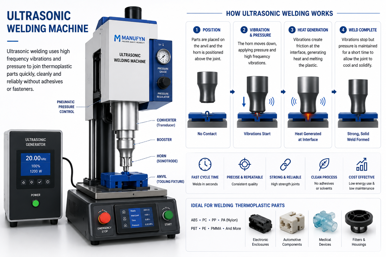
How the Machine Works
Every ultrasonic welding system consists of several precision-engineered components that work together to deliver controlled vibration energy. The generator converts standard electrical power into a high-frequency electrical signal, which is transformed into mechanical vibration by the converter. A booster adjusts the vibration amplitude before the horn transfers the energy into the plastic components being welded.
- High-frequency electrical power generation
- Mechanical vibration through piezoelectric technology
- Controlled amplitude adjustment
- Precision horn movement
- Programmable welding parameters
- Repeatable production quality
- Cycle times often under two seconds
20–40 kHz
Typical operating frequencies for thermoplastic ultrasonic welding systems.
<2 sec
Typical production cycle time for many engineering plastic assemblies.
No Adhesives
Creates strong molecular bonds without glue, solvents or mechanical fasteners.
24/7 Production
Designed for automated manufacturing cells and continuous production environments.
Major Components of an Ultrasonic Welding Machine
Every ultrasonic welding machine consists of precision-engineered components that work together to convert electrical energy into controlled mechanical vibrations. Understanding each component helps engineers optimize welding performance, improve process reliability and simplify preventive maintenance.
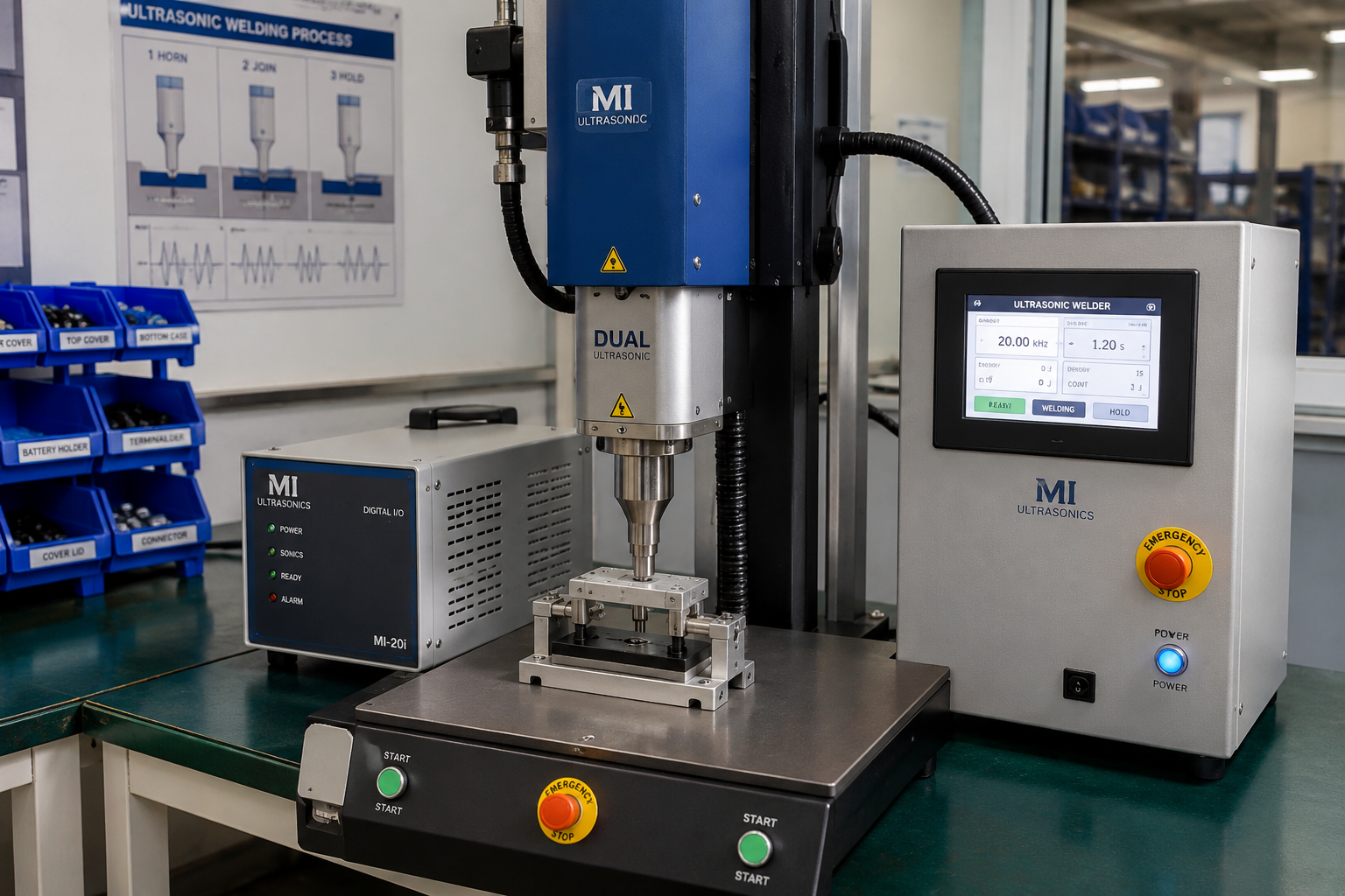
1. Generator (Power Supply)
The ultrasonic generator converts standard AC electrical power into a high-frequency electrical signal, typically operating at 20 kHz, 30 kHz or 40 kHz. It continuously monitors resonance and adjusts power output to maintain stable welding performance throughout the production cycle.
- Converts electrical energy
- Controls welding power
- Maintains resonance automatically
- Stores welding programs
- Supports multiple welding modes
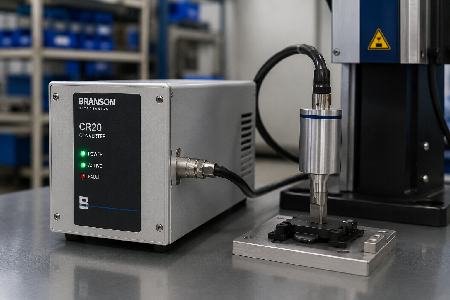
2. Converter (Transducer)
The converter transforms high-frequency electrical signals into mechanical vibrations using piezoelectric ceramic elements. This component forms the heart of the ultrasonic welding system and determines overall vibration efficiency.
- Piezoelectric technology
- Produces ultrasonic vibration
- High energy efficiency
- Precision engineered
- Long service life
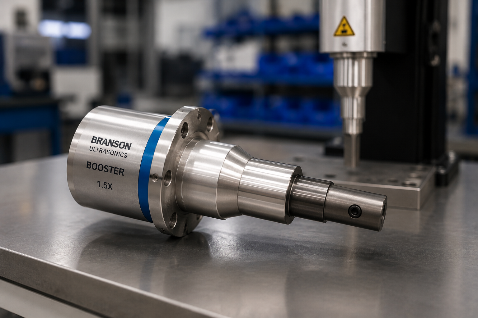
3. Booster
The booster adjusts vibration amplitude between the converter and the horn. Different booster ratios allow manufacturers to increase or decrease amplitude depending on material type, joint design and weld strength requirements.
- Adjusts vibration amplitude
- Optimizes welding energy
- Available in multiple gain ratios
- Supports process flexibility
- Improves weld consistency
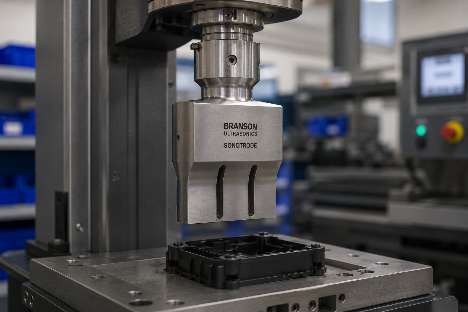
4. Horn (Sonotrode)
The horn, also known as a sonotrode, transfers ultrasonic vibration directly into the plastic component. Horn geometry is custom-designed for each application to ensure uniform energy distribution and minimize part deformation.
- Direct energy transfer
- Custom machined for each product
- Titanium or aluminum construction
- High dimensional accuracy
- Critical for weld quality
Actuation, Control & Support Systems
In addition to the generator, converter, booster and horn, several other components ensure accurate force application, part positioning and process control. These systems enable repeatable weld quality and reliable high-volume production.
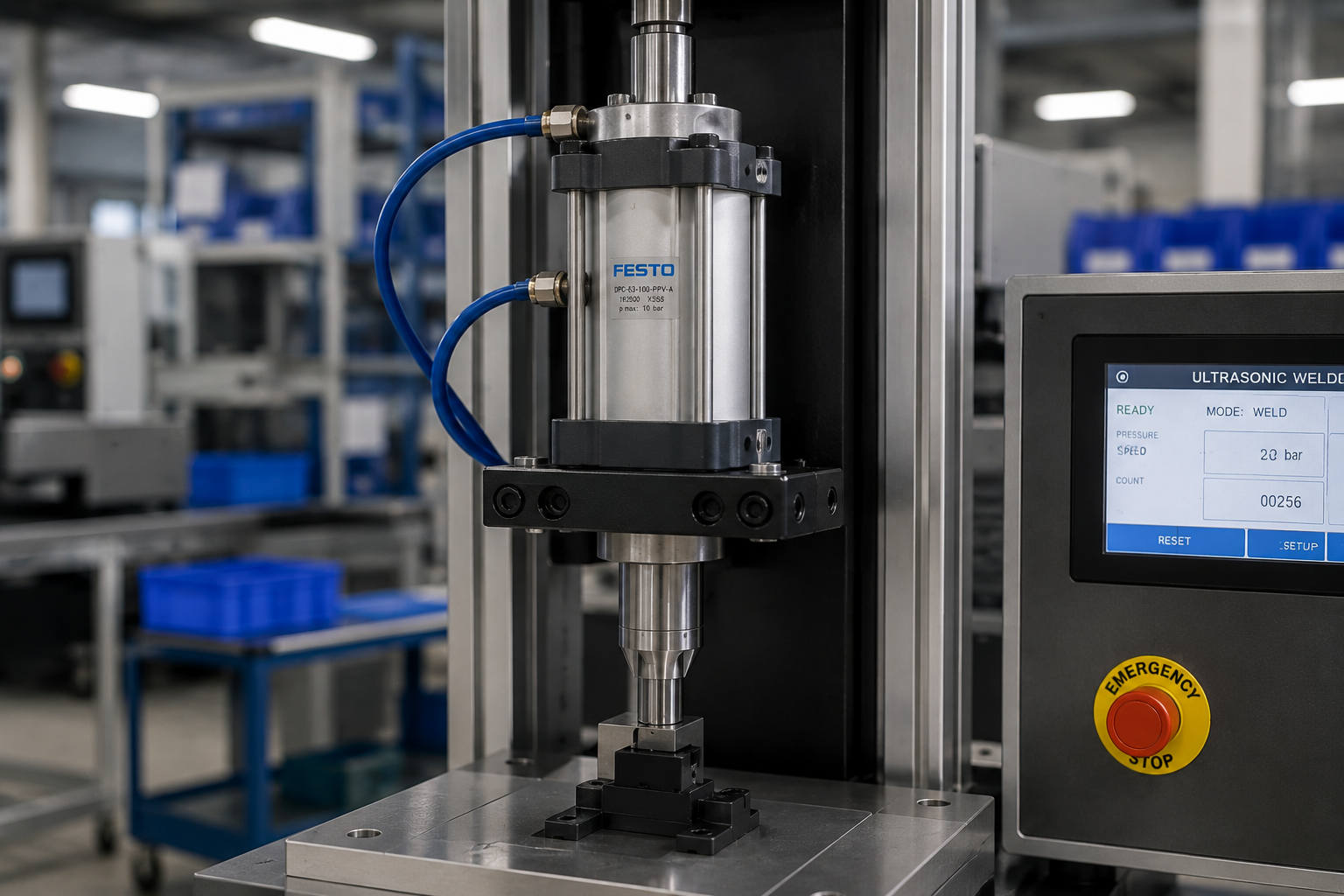
5. Pneumatic Actuator
Most conventional ultrasonic welding machines use a pneumatic cylinder to move the horn toward the workpiece while applying a controlled welding force. Stable air pressure is essential for consistent weld quality.
- Applies welding force
- Controls horn movement
- Fast production cycles
- Simple maintenance
- Widely used in production
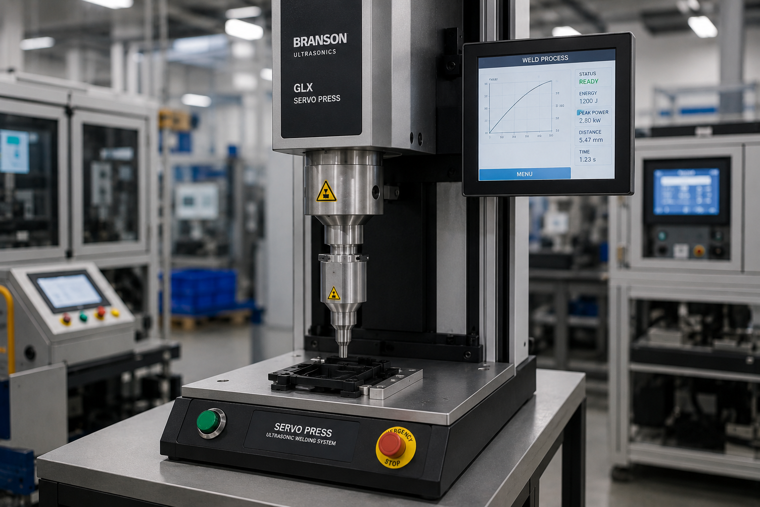
6. Servo Ultrasonic Welding Press
Servo-driven welding systems provide highly accurate control over position, force and velocity. These machines are commonly selected for medical devices, electronics and precision engineering applications where repeatability is critical.
- Programmable force control
- High positional accuracy
- Excellent repeatability
- Ideal for validation
- Supports Industry 4.0

7. Fixture (Anvil)
The fixture, commonly called the anvil, securely supports the plastic component during welding. A properly designed fixture minimizes vibration losses, prevents deformation and maintains dimensional accuracy throughout the welding cycle.
- Supports the workpiece
- Prevents movement
- Improves energy transfer
- Protects delicate features
- Ensures repeatability
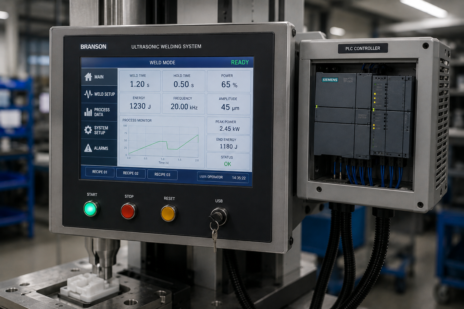
8. Controller (HMI / PLC)
Modern ultrasonic welding machines include a touchscreen HMI and PLC-based controller for programming weld parameters, monitoring production data and storing validated process recipes.
- Recipe management
- Production monitoring
- Alarm diagnostics
- Data logging
- User-friendly operation
| Frequency | Typical Applications | Amplitude | Best For |
|---|---|---|---|
| 20 kHz | Large automotive parts, industrial products | High | Large components requiring deeper energy penetration |
| 30 kHz | General engineering components | Medium | Balanced performance for most thermoplastic applications |
| 40 kHz | Medical devices, electronics, micro-components | Low | Small precision parts with delicate features and tight tolerances |
Engineering Recommendation
Selecting the appropriate ultrasonic welding machine configuration depends on part size, material properties, joint design, production volume and quality requirements. Larger engineering plastic components generally benefit from lower-frequency systems with higher amplitude, while miniature precision parts often require higher-frequency machines to reduce the risk of surface marking and component damage. At Manufyn, our engineering team supports customers from product design and injection molding through fixture development, ultrasonic welding, quality inspection and production validation to ensure repeatable manufacturing performance.
Ultrasonic Welding Modes & Process Controls
Modern ultrasonic welding systems offer multiple control modes to achieve consistent weld quality across different materials, joint geometries and production environments. Selecting the correct welding mode improves repeatability, reduces scrap and simplifies process validation for high-volume manufacturing.
Time Mode
Time Mode applies ultrasonic energy for a predetermined duration. It is one of the simplest control methods and is commonly used for stable production processes where material properties and component dimensions remain consistent.
- Easy to program
- Suitable for high-volume production
- Short setup time
- Ideal for consistent parts
- Widely used in consumer products
Energy Mode
Energy Mode monitors the total energy delivered during welding and automatically stops once the programmed energy value has been reached. This mode compensates for minor material or dimensional variations and improves weld consistency.
- Excellent repeatability
- Compensates for variation
- Improves process capability
- Suitable for engineering plastics
- Supports quality validation
Collapse Distance Mode
Collapse Distance Mode measures the amount of material collapse during welding rather than relying only on time or energy. This approach produces highly repeatable weld dimensions and is widely used for automotive and medical applications.
- Dimensional accuracy
- Excellent weld consistency
- Reduced flash variation
- Supports process validation
- Preferred for critical assemblies
Peak Power Mode
Peak Power Mode monitors the highest power level reached during welding. It is particularly useful when process stability depends on limiting the maximum energy transferred to delicate plastic components.
- Protects sensitive parts
- Monitors peak load
- Supports electronics assembly
- Reduces cosmetic defects
- Useful for thin-wall components
| Control Mode | Primary Parameter | Best Applications | Advantages |
|---|---|---|---|
| Time Mode | Weld Time | Stable production environments | Simple setup and fast production |
| Energy Mode | Total Energy | Engineering plastics | Compensates for material variation |
| Collapse Distance Mode | Material Collapse | Automotive and Medical | Highest dimensional consistency |
| Peak Power Mode | Maximum Power | Precision electronics | Protects delicate components |
| Absolute Distance Mode | Final Position | Precision assemblies | Controls finished assembly height |
| Ground Detect Mode | Electrical Contact | Specialized applications | Detects conductive contact events |
Advanced Process Monitoring
High-performance ultrasonic welding machines continuously monitor parameters such as trigger force, weld force, amplitude, weld time, peak power, energy input, collapse distance, hold time and final assembly height. Recording these values for every cycle supports Statistical Process Control (SPC), Production Part Approval Process (PPAP), process capability studies (Cp/Cpk) and complete production traceability. For regulated industries such as medical devices, automotive and electronics, digital process monitoring helps maintain consistent product quality while simplifying audits and validation activities.
Quality Control in Ultrasonic Welding
Producing a visually acceptable weld is only one aspect of quality assurance. High-performance ultrasonic welded assemblies must consistently meet dimensional, mechanical and functional requirements throughout production. A robust inspection strategy combines process monitoring with destructive and non-destructive testing to ensure every component meets customer specifications.
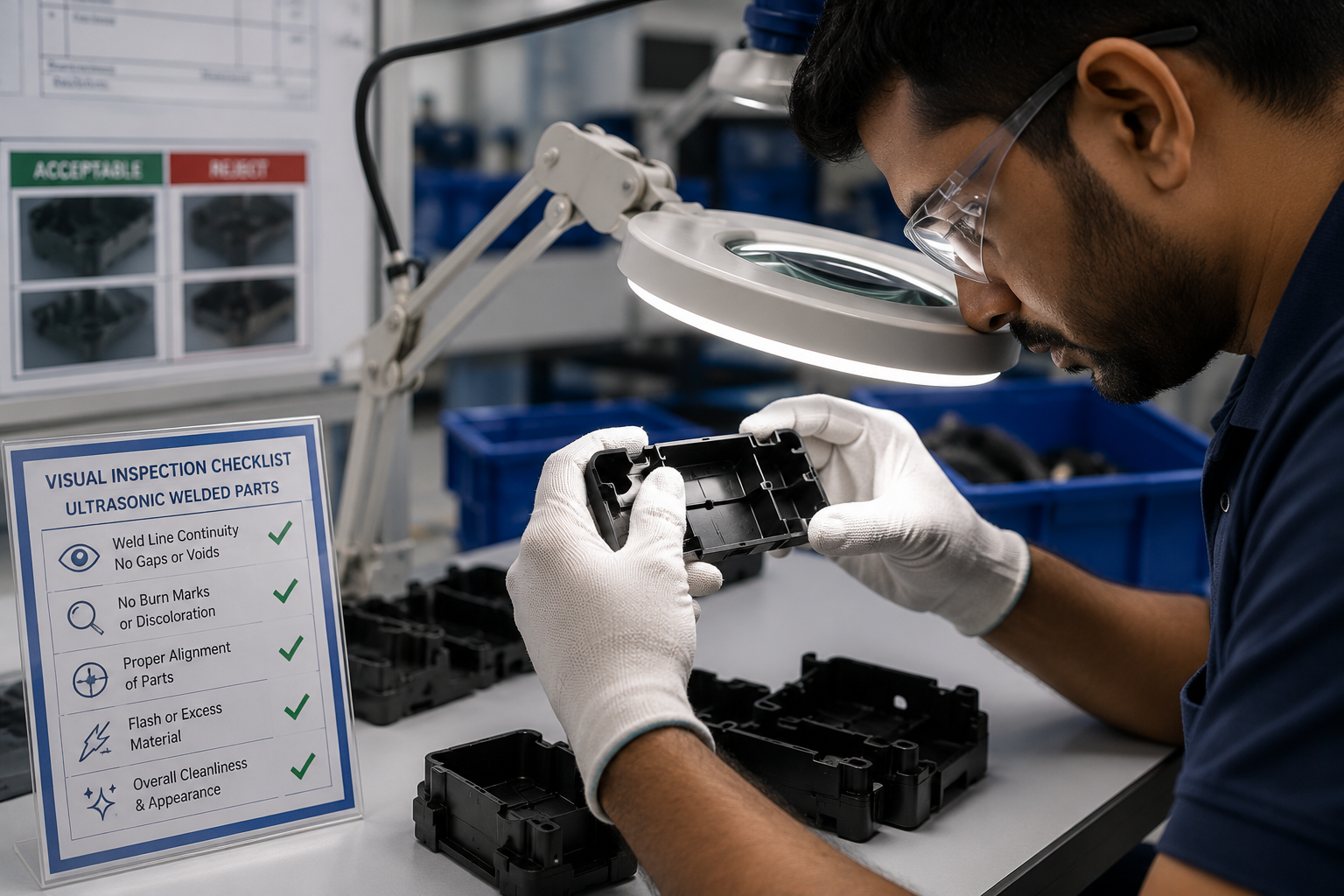
1. Visual Inspection
Visual inspection is the first quality verification step after welding. Operators examine each assembly for cosmetic appearance, weld flash, surface damage, discoloration and incomplete fusion before the parts proceed to the next manufacturing stage.
- Check weld continuity
- Inspect for excessive flash
- Look for cracks or deformation
- Verify part alignment
- Confirm cosmetic appearance
- Inspect witness lines
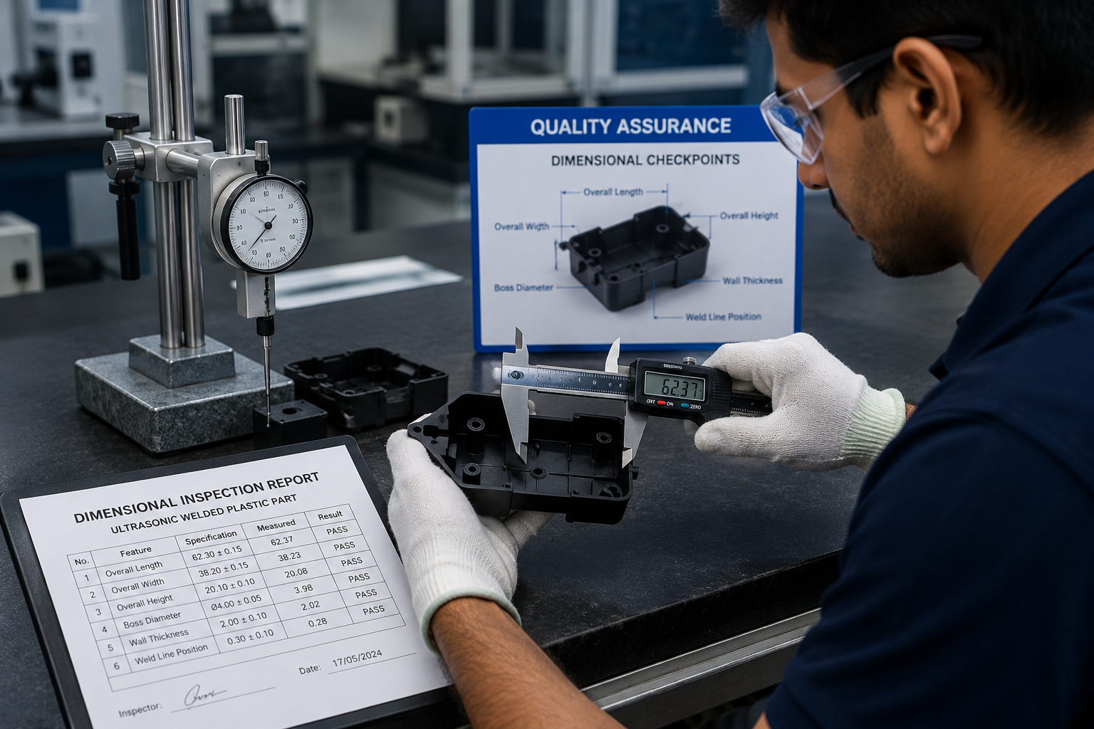
2. Dimensional Inspection
Critical dimensions should be verified after welding because localized melting can affect final assembly height and overall geometry. Precision measuring equipment helps ensure dimensional compliance with engineering drawings.
- Digital calipers
- Height gauges
- CMM inspection
- Go/No-Go gauges
- Profile measurement
- GD&T verification
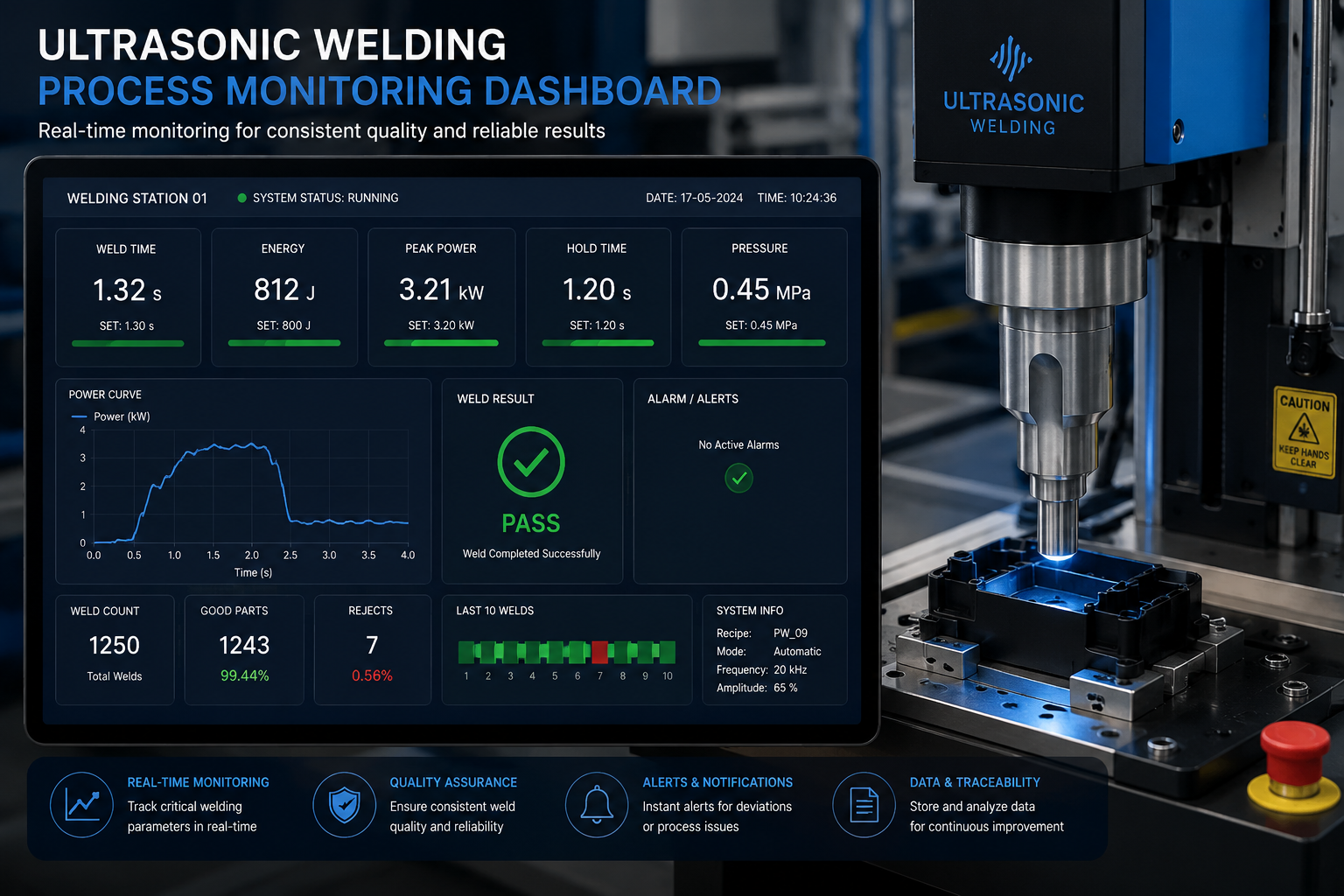
3. Real Time Process Monitoring
Modern ultrasonic welders continuously record process parameters including weld time, amplitude, energy, trigger force, collapse distance and peak power. Monitoring these values enables early detection of process drift before defective products are produced.
- Automatic parameter logging
- SPC compatibility
- Production traceability
- Alarm generation
- Trend analysis
- Recipe validation
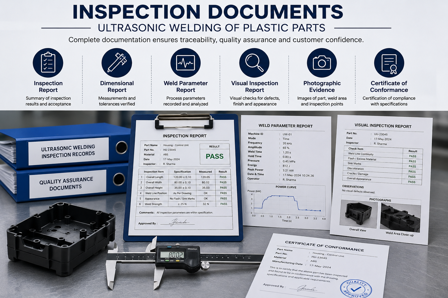
4. Production Documentation
Inspection reports, machine settings, process validation records and dimensional measurements provide complete traceability for every production batch. Documentation is particularly important for automotive, aerospace and medical manufacturing.
- Inspection reports
- Control plans
- PPAP documentation
- Lot traceability
- Operator records
- Calibration records
Mechanical Testing of Ultrasonic Welded Components
Before an ultrasonic welding process is released for production, engineers validate the joint using mechanical, dimensional and functional testing. Validation confirms that the welded assembly meets strength, sealing and durability requirements throughout its expected service life.
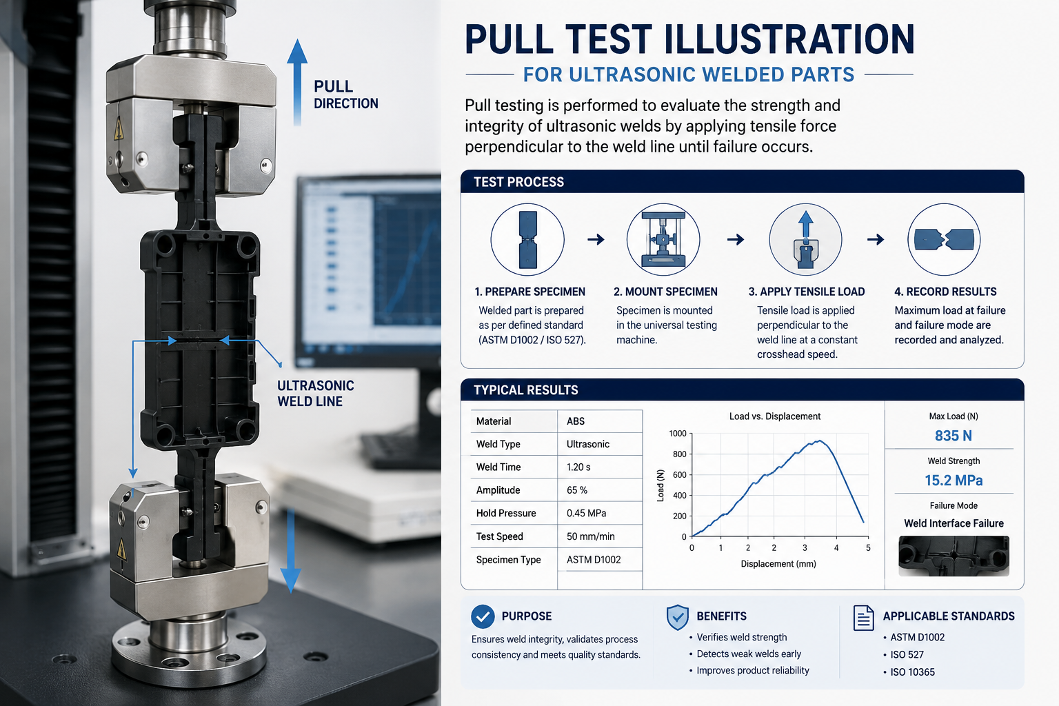
1. Tensile (Pull) Test
A tensile pull test measures the maximum force required to separate two welded plastic components. It is one of the most common destructive tests used to qualify ultrasonic welds.
- Measures ultimate weld strength
- Detects weak fusion zones
- Validates process capability
- Supports PPAP documentation
- Compares prototype and production parts
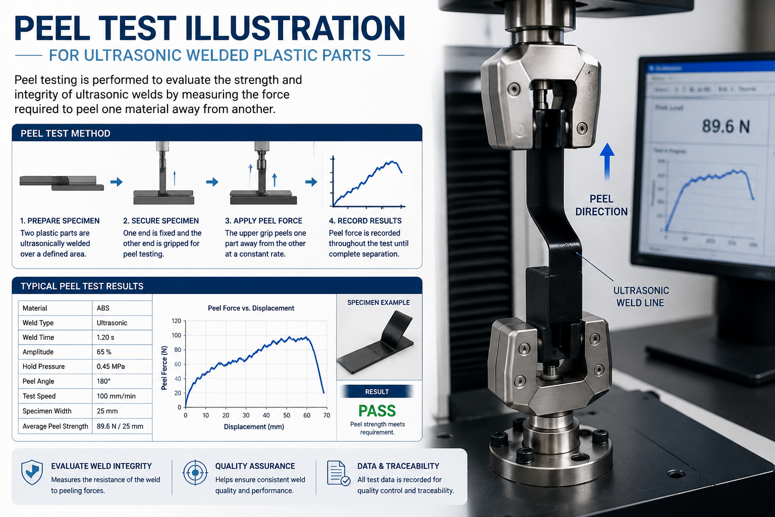
2. Peel Test
Peel testing evaluates the resistance of welded joints subjected to peeling forces. It is commonly performed on thin-wall plastic assemblies and packaging applications.
- Measures bond integrity
- Evaluates thin-wall components
- Identifies incomplete fusion
- Supports material comparison
- Useful during design validation
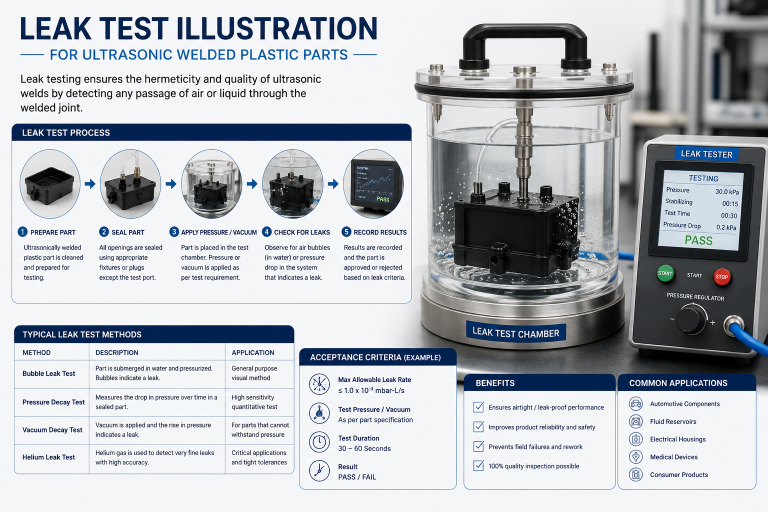
3. Leak Testing
Leak testing verifies that welded assemblies achieve the required sealing performance. Depending on the application, testing may use air pressure, vacuum decay, helium leak detection or water immersion.
- Detects microscopic leaks
- Validates hermetic seals
- Supports automotive products
- Required for medical devices
- Suitable for fluid reservoirs
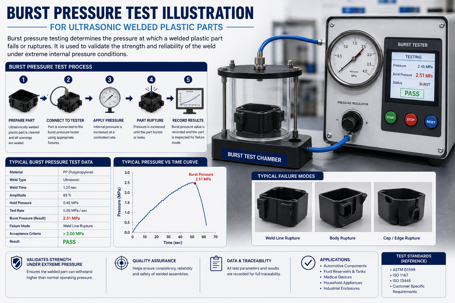
4. Burst Pressure Test
Pressure-containing components are subjected to burst testing to verify the maximum pressure the welded joint can withstand before failure.
- Measures pressure resistance
- Evaluates safety margin
- Supports fluid systems
- Common in automotive applications
- Used for filter housings and reservoirs
| Validation Method | Purpose | Destructive | Typical Industries |
|---|---|---|---|
| Tensile (Pull) Test | Measure weld strength | Yes | Automotive, Medical, Industrial |
| Peel Test | Evaluate bond quality | Yes | Packaging, Electronics |
| Leak Test | Verify sealing performance | No | Medical, Automotive |
| Burst Pressure Test | Validate pressure resistance | Yes | Fluid Handling Systems |
| Dimensional Inspection | Verify critical dimensions | No | All Industries |
| Visual Inspection | Detect cosmetic defects | No | All Industries |
Engineering Validation Best Practices
Mechanical testing should be complemented by dimensional inspection, statistical process control, and documented validation plans. For safety-critical products, engineers should establish acceptance criteria before production begins and perform periodic revalidation after tooling maintenance or material changes. Combining destructive testing with process monitoring helps ensure long-term manufacturing consistency while reducing the risk of field failures.
Common Ultrasonic Welding Defects and Troubleshooting Guide
Even with advanced ultrasonic welding equipment, defects can occur if machine settings, tooling, material condition or part design are not optimized. A structured troubleshooting approach helps manufacturers quickly identify root causes, minimize downtime and improve first-pass yield.
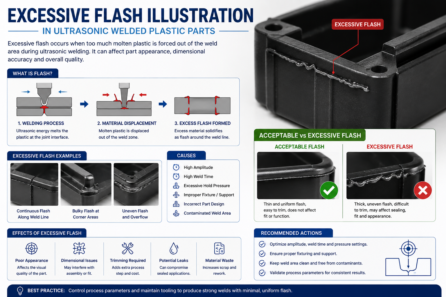
Excessive Flash
Flash occurs when too much molten plastic escapes from the joint during welding. While a small amount of flash may be acceptable, excessive flash often affects product appearance and dimensional accuracy.
- Weld pressure too high
- Excessive amplitude
- Long weld time
- Improper energy director
- Incorrect fixture support
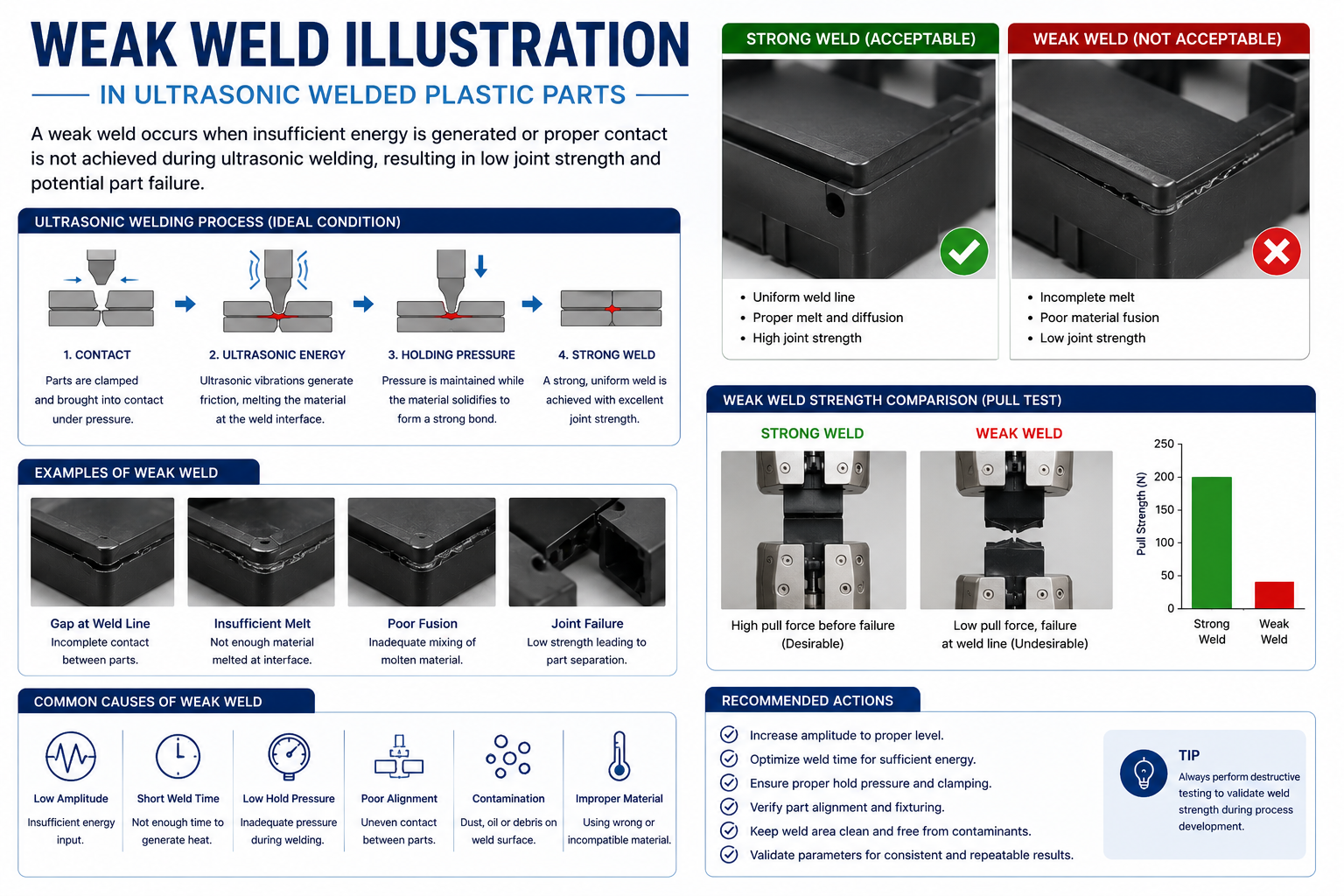
Weak or Incomplete Weld
Insufficient fusion usually results in poor mechanical strength and premature joint failure during functional testing or field use.
- Low weld energy
- Short weld time
- Poor horn alignment
- Moisture in material
- Incorrect joint design
 n
n
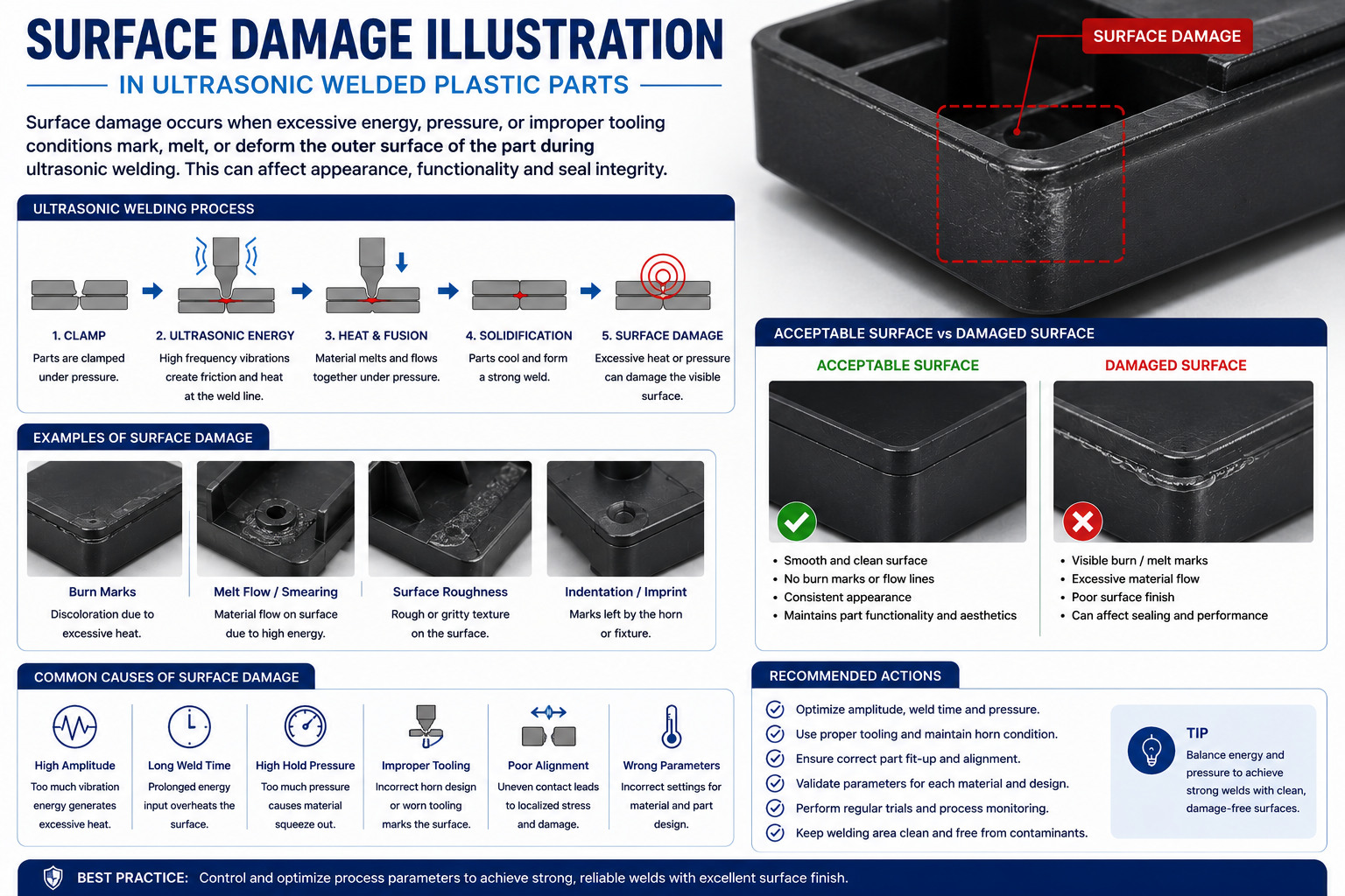
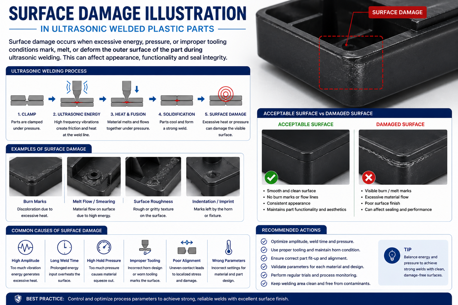
Surface Marks & Burn Damage
Localized overheating may produce burn marks, whitening or cosmetic damage on visible plastic surfaces. These defects are particularly critical for consumer products and medical devices.
- Excessive amplitude
- High trigger force
- Poor horn finish
- Excessive welding energy
- Incorrect horn contact area
Stress Cracks After Welding
Residual stress caused by improper process parameters or sharp internal corners can create cracks immediately after welding or during product use.
- High residual stress
- Sharp corner geometry
- Material incompatibility
- Poor fixture support
- Over-welding
| Defect | Possible Cause | Recommended Solution |
|---|---|---|
| Excessive Flash | High pressure or long weld time | Reduce amplitude, optimize weld energy and improve joint design |
| Weak Weld | Insufficient energy | Increase energy, optimize horn alignment and verify material condition |
| Burn Marks | Excessive vibration | Reduce amplitude and improve horn contact |
| Part Cracking | Residual stress | Improve corner radii, reduce pressure and optimize cooling |
| Misalignment | Poor fixture design | Redesign fixture and improve part location features |
| Poor Hermetic Seal | Incomplete fusion | Increase energy and verify joint geometry |
| Horn Sticking | Excessive heat | Polish horn surface and optimize process settings |
| Inconsistent Weld Strength | Material variation or unstable machine settings | Dry material, calibrate equipment and validate process parameters |
Engineering Best Practices for Process Optimization
Many ultrasonic welding defects originate long before production begins. Proper part design, optimized energy directors, accurate fixture design, controlled moisture content, validated machine settings and preventive maintenance significantly improve weld quality. Recording weld energy, collapse distance, peak power and cycle-to-cycle variation allows engineers to detect process drift early and maintain stable production over millions of components.
Industries Using Ultrasonic Welding
Ultrasonic welding has become one of the preferred joining technologies for thermoplastic components because it produces clean, repeatable and high-strength joints without adhesives, screws or solvents. From automotive manufacturing to medical devices, the process supports high-volume production while maintaining excellent dimensional accuracy and short cycle times.
Automotive Industry
Modern vehicles contain hundreds of welded plastic assemblies. Ultrasonic welding enables manufacturers to produce lightweight, leak-free and vibration-resistant components suitable for demanding automotive environments.
- Sensor housings
- Air intake systems
- Fluid reservoirs
- Lighting assemblies
- Dashboard components
- EV battery housings
Medical Devices
Medical manufacturers rely on ultrasonic welding because it creates particulate-free joints with precise process control. The technology is widely used in disposable and reusable medical products.
- Diagnostic cartridges
- IV connectors
- Surgical instruments
- Filter housings
- Drug delivery devices
- Laboratory consumables
Electronics & Electrical Equipment
Electronic products require strong and cosmetically attractive plastic joints. Ultrasonic welding eliminates visible fasteners while protecting delicate electronic assemblies.
- Switchgear housings
- Electrical connectors
- Battery packs
- PCB enclosures
- Charging systems
- Consumer electronics
Industrial Equipment
Industrial machinery manufacturers use ultrasonic welding for durable plastic components that must withstand repeated mechanical loading, chemicals and demanding operating environments.
- Pumps
- Filtration systems
- Valve assemblies
- Industrial sensors
- Automation equipment
- Robotic components
| Industry | Typical Products | Key Requirement | Why Ultrasonic Welding? |
|---|---|---|---|
| Automotive | Sensors, reservoirs, lighting | Strength & leak resistance | Fast production with repeatable quality |
| Medical | Diagnostic devices, filters | Clean joining process | No adhesives or contaminants |
| Electronics | Battery packs, connectors | Precision assembly | Low heat transfer to electronics |
| Industrial | Automation & fluid systems | Durability | High joint strength |
| Consumer Products | Appliances & personal care | Appearance | Hidden joints with short cycle time |
| Aerospace | Interior plastic components | Weight reduction | Reliable and lightweight assemblies |
Why Manufacturers Choose Manufyn for Ultrasonic Welded Components
At Manufyn, ultrasonic welding is integrated into a complete manufacturing workflow that includes product design support, DFM reviews, precision injection molding, fixture development, CNC machining, quality inspection and production validation. This integrated approach reduces supplier coordination, improves communication and ensures consistent quality from prototype development through mass production.
Ultrasonic Welding Performance by Plastic Material
Not all thermoplastics respond to ultrasonic welding in the same way. Material stiffness, melt temperature, moisture absorption and molecular structure all influence weld strength and process stability. Selecting the correct plastic during product development helps achieve stronger joints, faster cycle times and improved production consistency.
ABS (Acrylonitrile Butadiene Styrene)
ABS is one of the easiest engineering plastics to weld ultrasonically. Its rigidity and predictable melting behavior enable fast cycle times and excellent cosmetic results, making it suitable for electrical housings, automotive trim and consumer products.
- Excellent weldability
- Fast cycle times
- High cosmetic quality
- Good impact resistance
- Suitable for electronics
Polycarbonate (PC)
Polycarbonate produces strong ultrasonic welds with excellent dimensional stability. Careful control of amplitude and pressure helps prevent surface whitening and stress cracking, especially for transparent components.
- Very high strength
- Excellent transparency
- Good impact resistance
- Ideal for medical devices
- Requires optimized parameters
Nylon (PA6 & PA66)
Nylon is widely used in automotive and industrial applications. Since it absorbs moisture from the environment, proper material drying before welding is essential for achieving consistent weld strength and minimizing void formation.
- High mechanical strength
- Excellent wear resistance
- Moisture sensitive
- Suitable for structural parts
- Excellent for automotive applications
Polypropylene (PP)
Polypropylene can be ultrasonically welded successfully, although its lower stiffness and higher damping characteristics generally require optimized joint designs and process settings compared with amorphous plastics.
- Excellent chemical resistance
- Lightweight
- Low material cost
- Good fatigue resistance
- Requires optimized energy directors
| Material | Weldability | Typical Applications | Engineering Considerations |
|---|---|---|---|
| ABS | ★★★★★ | Electronics, Automotive Interiors | Easy processing and excellent cosmetic finish |
| Polycarbonate (PC) | ★★★★★ | Medical Devices, Lighting | Control pressure to reduce stress whitening |
| Nylon (PA6 / PA66) | ★★★★☆ | Automotive, Industrial Components | Dry material before welding |
| Glass Filled Nylon | ★★★★☆ | Structural Components | Higher horn wear due to glass fibers |
| Polypropylene (PP) | ★★★☆☆ | Packaging, Fluid Systems | Requires optimized joint geometry |
| PBT | ★★★★☆ | Electrical Connectors | Excellent dimensional stability |
| PC/ABS Blend | ★★★★★ | Consumer Electronics | Excellent balance of toughness and weldability |
| PEEK | ★★★☆☆ | Medical & Aerospace | Requires specialized process development |
| PEI (ULTEM) | ★★★★☆ | Medical, Aerospace | High-temperature engineering plastic |
| PMMA (Acrylic) | ★★★★☆ | Lighting & Display Products | Avoid excessive amplitude to prevent cracking |
Material Selection Recommendations
Material selection should consider not only weldability but also the final application’s mechanical, thermal and environmental requirements. Amorphous plastics such as ABS and Polycarbonate generally offer wider processing windows and are easier to weld, while semi-crystalline materials such as Nylon and Polypropylene often require more precise control of joint design, moisture content and process parameters. Early Design for Manufacturing (DFM) reviews help optimize material choice, tooling and ultrasonic welding performance before production begins.
Advantages and Limitations of Ultrasonic Welding
Ultrasonic welding has become one of the most widely adopted joining technologies for thermoplastic components because it combines exceptional speed, precision and repeatability. Compared with mechanical fasteners, adhesives and solvent bonding, ultrasonic welding enables manufacturers to reduce assembly time while producing clean, high-strength joints suitable for demanding industrial applications.
Key Advantages
- Extremely fast cycle times, often under two seconds.
- No adhesives, solvents or curing time required.
- Creates strong and repeatable weld joints.
- Produces clean, aesthetically pleasing assemblies.
- Minimal heat affected zone.
- Low operating cost after tooling investment.
- Suitable for fully automated production lines.
- Excellent dimensional repeatability.
- Supports high-volume manufacturing.
- Low energy consumption.
- Environmentally friendly joining process.
- No consumables during production.
- Ideal for leak-proof plastic assemblies.
- Excellent traceability using digital process monitoring.
- Compatible with Industry 4.0 manufacturing systems.
- Reduced assembly labor.
- Lower maintenance compared to adhesive dispensing systems.
- Minimal production floor space.
- Suitable for cleanroom manufacturing.
- Consistent weld quality across millions of production cycles.
Limitations
- Limited primarily to thermoplastic materials.
- Joint design must be optimized during product development.
- Large components may require specialized equipment.
- Initial tooling investment is higher than manual assembly.
- Horn design is application-specific.
- Some semi-crystalline plastics require tighter process control.
- High glass-filled materials increase horn wear.
- Moisture-sensitive materials require proper drying.
- Very complex geometries may require custom fixtures.
- Thin cosmetic surfaces can be damaged if parameters are not optimized.
- Process validation is required for safety-critical applications.
- Different materials generally cannot be welded together unless specifically validated.
| Feature | Ultrasonic Welding | Adhesive Bonding | Mechanical Fasteners |
|---|---|---|---|
| Cycle Time | Less than 2 seconds | Minutes to hours | Several seconds |
| Consumables | None | Adhesive required | Screws, inserts or rivets |
| Automation | Excellent | Moderate | Good |
| Appearance | Excellent | Good | Visible hardware |
| Leak Tightness | Excellent | Good | Often requires seals |
| Environmental Impact | Low | Chemical waste possible | Additional materials required |
| Production Cost | Low for high volumes | Medium | Medium to High |
Engineering Perspective
Ultrasonic welding offers the greatest return on investment when products are designed specifically for the process. Features such as energy directors, shear joints, accurate locating features and rigid fixture support significantly improve weld consistency and reduce cycle times. Combining Design for Manufacturing (DFM), precision injection molding, tooling expertise and process validation allows manufacturers to achieve reliable production with minimal defects and lower overall assembly costs.
Ultrasonic Welding vs Other Plastic Joining Technologies
Choosing the right joining technology depends on component geometry, production volume, material compatibility, required joint strength, cosmetic requirements and manufacturing cost. While ultrasonic welding is often the preferred solution for thermoplastic assemblies, other joining methods may be better suited for larger parts, specialized materials or unique application requirements.
Why Ultrasonic Welding Leads Modern Manufacturing
Ultrasonic welding delivers high production efficiency while eliminating adhesives, screws and curing time. It is particularly effective for small to medium-sized thermoplastic components requiring excellent cosmetic appearance and consistent mechanical performance.
- Cycle time typically under 2 seconds
- No consumables during production
- Excellent automation capability
- High repeatability
- Low operating cost
- Minimal heat affected zone
- Ideal for high-volume manufacturing
- Supports Industry 4.0 monitoring
When Other Joining Processes May Be Preferred
Alternative joining technologies are selected when components exceed ultrasonic welding size limits, require continuous weld seams over large areas or involve material combinations unsuitable for ultrasonic energy transfer.
- Large automotive tanks
- Very thick wall components
- Transparent laser-weldable assemblies
- Circular components requiring rotational joints
- Products requiring metal inserts
- Extremely complex joint geometries
- Low-volume manual production
| Parameter | Ultrasonic Welding | Laser Welding | Vibration Welding | Hot Plate Welding | Spin Welding | Adhesive Bonding |
|---|---|---|---|---|---|---|
| Typical Cycle Time | <2 sec | 5–15 sec | 10–30 sec | 20–60 sec | 3–10 sec | Minutes to hours |
| Automation | Excellent | Excellent | Excellent | Very Good | Very Good | Moderate |
| Production Cost | Low | High | Medium | Medium | Low | Medium |
| Tooling Cost | Medium | High | High | High | Medium | Low |
| Joint Appearance | Excellent | Excellent | Good | Moderate | Good | Good |
| Leak Tight Joints | Excellent | Excellent | Excellent | Excellent | Excellent | Depends on adhesive |
| Suitable for Large Parts | Limited | Limited | Excellent | Excellent | No | Yes |
| Environmental Impact | Very Low | Low | Low | Medium | Low | Chemical waste possible |
| Typical Industries | Medical, Automotive, Electronics | Medical, Electronics | Automotive | Automotive, Tanks | Caps & Filters | General Assembly |
Selecting the Right Joining Technology
There is no universal joining process for every plastic assembly. Engineers should evaluate component size, material type, sealing requirements, structural loading, cosmetic expectations, annual production volume and total manufacturing cost before selecting a process. For most small and medium-sized thermoplastic components, ultrasonic welding provides the best balance of speed, quality, automation and long-term production cost. However, large structural assemblies, rotational components or specialized applications may benefit from vibration welding, hot plate welding, spin welding or laser plastic welding.
Your Manufacturing Partner for Precision Ultrasonic Welding
At Manufyn, ultrasonic welding is integrated into a complete manufacturing ecosystem rather than being offered as a standalone process. From product design and engineering support to tooling, injection molding, CNC machining, ultrasonic welding, assembly and quality validation, we help customers simplify their supply chain while ensuring consistent product quality and on-time delivery.
Complete Manufacturing Solution
Our customers benefit from a single engineering partner capable of managing every stage of product development and production.
- Design for Manufacturing (DFM)
- Prototype development
- Injection mold design
- Precision injection molding
- Ultrasonic welding
- CNC machining
- Product assembly
- Quality inspection
- Export-ready packaging
- Global logistics support
Industries We Serve
We manufacture precision components for customers across multiple industries with demanding quality and performance requirements.
- Automotive
- Electric Vehicles (EV)
- Medical Devices
- Industrial Automation
- Consumer Electronics
- Electrical & Switchgear
- Fluid Handling
- Robotics
- Renewable Energy
- Industrial Equipment
Our Manufacturing Workflow
Design Review
DFM analysis, material selection and joint design optimization.
Tooling
Injection molds, fixtures, ultrasonic horns and production tooling.
Production
Injection molding, CNC machining and ultrasonic welding.
Inspection
Dimensional inspection, functional testing and production validation.
Delivery
Packaging, documentation and worldwide shipment support.
100%
Engineering support from concept through production.
24 hrs
Typical quotation response for complete manufacturing projects.
Global
Serving customers across North America, Europe and other international markets.
End to End
Integrated manufacturing, inspection, assembly and logistics under one partner.
Ready to Start Your Ultrasonic Welding Project?
Whether you need prototype quantities or high-volume production, our engineering team can help optimize your product for manufacturability, reduce production costs and deliver consistent quality. Share your CAD files or technical drawings with us for a detailed engineering review and competitive quotation.
Ultrasonic Welding FAQ
Below are answers to some of the most common questions engineers, product designers and purchasing teams ask when selecting ultrasonic welding for plastic components.
1. What is ultrasonic welding?
2. How does ultrasonic welding work?
3. Which plastics can be ultrasonically welded?
4. Can ABS be ultrasonically welded?
5. Can Nylon be ultrasonically welded?
6. Is ultrasonic welding stronger than adhesive bonding?
7. What industries use ultrasonic welding?
8. How long does an ultrasonic welding cycle take?
9. Does ultrasonic welding require adhesives?
10. What is an energy director?
11. Is ultrasonic welding environmentally friendly?
12. Can glass-filled Nylon be ultrasonically welded?
13. What is the most common ultrasonic welding frequency?
14. Is ultrasonic welding suitable for medical devices?
15. Can ultrasonic welding create watertight joints?
16. What materials cannot be ultrasonically welded?
17. Can two different plastics be ultrasonically welded?
18. What factors affect weld strength?
19. What is welding amplitude?
20. What is hold time in ultrasonic welding?
21. What is collapse distance?
22. Can ultrasonic welding be fully automated?
23. What is the typical production rate?
24. What are the most common welding defects?
25. How can ultrasonic welding defects be prevented?
26. Does ultrasonic welding generate smoke?
27. Is ultrasonic welding safe for operators?
28. How long does an ultrasonic horn last?
29. How often should ultrasonic welding equipment be calibrated?
30. Can transparent plastic parts be ultrasonically welded?
31. Is ultrasonic welding suitable for automotive parts?
32. Is ultrasonic welding suitable for food-grade products?
33. What component size is best suited for ultrasonic welding?
34. Is ultrasonic welding economical for low-volume production?
35. How do I choose the right ultrasonic welding partner?
36. What production volume is ideal for ultrasonic welding?
37. Does ultrasonic welding require special joint designs?
38. Can ultrasonic welding be used for leak-proof assemblies?
39. What quality checks are performed after welding?
40. Can inserts be combined with ultrasonic welding?
41. Does color affect ultrasonic welding?
42. Is ultrasonic welding suitable for cleanroom manufacturing?
43. Can recycled plastics be ultrasonically welded?
44. Can ultrasonic welding be validated for regulated industries?
45. What information should I provide for a quotation?
46. Can Manufyn support prototype and production quantities?
47. Does Manufyn provide Design for Manufacturing (DFM) support?
48. Which countries does Manufyn serve?
49. How quickly can I receive a quotation?
50. How can I start my ultrasonic welding project with Manufyn?
Ready to Manufacture Your Ultrasonically Welded Components?
Whether you need rapid prototypes, low-volume production or high-volume manufacturing, Manufyn provides complete engineering support from design review and tooling to injection molding, ultrasonic welding, quality inspection and worldwide delivery. Our team works closely with OEMs, product designers and procurement professionals to deliver reliable, cost-effective manufacturing solutions.