Manufyn reviews ribs and bosses to prevent cracking and sink.
In injection molded plastic parts, ribs and bosses are not cosmetic features—they are structural and functional design elements that directly influence part performance, tooling complexity, cycle time, and long-term reliability. A well-executed rib and boss design guide focuses on how these features replace thick walls, manage loads, and enable assembly without introducing molding defects.
Why ribs are engineered into injection molded parts
Ribs are primarily used to:
- Increase bending stiffness without increasing nominal wall thickness
- Control deflection under load
- Reduce material usage while maintaining strength
- Improve dimensional stability during service
From an engineering standpoint, ribs shift the neutral axis of a plastic section, allowing the part to resist bending moments more efficiently than simply thickening walls. This is why rib design in injection molding is preferred over thick sections, which cause sink marks, voids, and long cooling times.
Why bosses are critical functional features
Bosses serve as:
- Fastening points for screws or inserts
- Alignment features during assembly
- Load transfer points between components
Unlike ribs, which distribute loads, bosses concentrate loads, making injection molding boss design far more sensitive to stress concentration, creep, and cracking. Poorly designed injection molding bosses are one of the most common causes of post-assembly failures.
Impact of rib and boss design on manufacturability
Improper rib and boss design leads to:
- Sink marks and cosmetic read-through
- Warpage due to uneven cooling
- Mold filling hesitation and weld lines
- Increased tooling cost due to corrective actions
This is why ribs and bosses must be designed together, not in isolation, using a design-for-manufacturability mindset from the earliest CAD stage.
Engineering Role of Ribs and Bosses in Injection Molded Parts

Ribs and bosses play different but complementary roles in injection molded parts. Understanding this difference is essential before getting into detailed rib design injection molding or injection molding boss design rules.
At a high level, ribs are used to distribute loads, while bosses are used to carry and transfer localized loads. This distinction explains why ribs are generally forgiving in design, whereas bosses are often the first features to fail.
Ribs vs Thick Walls: Why Ribs Are Preferred
In injection molding, increasing wall thickness to improve strength creates more problems than it solves. Thick walls cool unevenly, trap heat, and lead to sink marks and voids. Rib design in injection molding avoids these issues by improving stiffness through geometry rather than mass.
Ribs increase bending stiffness by shifting the neutral axis of the part. As a result, the part resists deformation more effectively without increasing nominal wall thickness. This allows manufacturers to reduce material usage while maintaining strength and dimensional stability.
How Bosses Function Differently From Ribs
Injection molding bosses are designed for functional purposes such as fastening, alignment, and load transfer. Unlike ribs, bosses concentrate stress at specific locations, especially at the boss base where it meets the nominal wall.
Because of this, injection molding boss design is far more sensitive to geometry, material selection, and reinforcement strategy. Small design errors in bosses often lead to cracking during screw insertion or creep failure during service.
Impact of Rib and Boss Design on Production
Poor rib and boss design does not only affect part performance — it directly affects manufacturing efficiency. Incorrect rib placement increases cooling time and warpage, while weak boss design frequently forces tooling changes after trials.
The table below summarizes how ribs and bosses influence production outcomes.
| Feature | Primary Role | Manufacturing Impact |
|---|---|---|
| Ribs | Improve stiffness | Faster cooling, lower material usage |
| Bosses | Support assembly loads | Higher risk of cracking if poorly designed |
| Poor integration | Stress concentration | Tooling rework, scrap, delays |
Why Ribs and Bosses Must Be Designed Together
Ribs and bosses should never be designed in isolation. Poor rib placement can cause sink marks around bosses, while bosses without rib reinforcement often fail during assembly. When ribs and bosses are designed together, loads are distributed more evenly and long-term reliability improves.
This integrated approach is the foundation of production-ready rib and boss design.
Struggling with sink marks or warpage caused by rib design?
Get your rib geometry reviewed before tooling and avoid costly mold changes.
Rib Design in Injection Molding: Engineering Fundamentals
Rib design in injection molding focuses on improving part stiffness and stability without increasing wall thickness. Instead of adding bulk material, ribs allow strength to be added only where it is required. This makes ribs one of the most effective structural features in injection molded plastic parts.
However, ribs that are dimensionally correct but poorly oriented or badly integrated often create sink marks, warpage, or flow issues. For this reason, injection molding rib design must balance structural performance with moldability.
Structural Function of Ribs
Ribs improve stiffness by changing how loads move through a plastic part. When a rib is added, the neutral axis of the section shifts, allowing the part to resist bending more effectively than a flat wall of the same thickness.
Compared to thick walls, ribs deliver the same or higher stiffness with less material. At the same time, ribs cool faster and more uniformly, which reduces internal stress and improves dimensional stability after molding.
In practical terms, rib design injection molding is preferred whenever strength is needed but surface quality and cycle time must be protected.
Rib Orientation and Load Direction
Rib orientation has a direct impact on how effective a rib actually is. Ribs placed without considering load direction often add weight without improving performance.
Ribs oriented perpendicular to bending loads significantly increase stiffness and reduce deflection. In contrast, ribs aligned parallel to the load path contribute very little structural benefit and may introduce torsional weakness instead.
For functional plastic parts, ribs should always follow expected load paths rather than cosmetic or symmetric patterns.
Rib Geometry Parameters That Affect Moldability
The geometry of a rib determines not only its strength but also how well it molds. Rib thickness, height, and spacing directly influence polymer flow, cooling behavior, and surface quality.
| Rib Parameter | Why It Matters in Injection Molding |
|---|---|
| Rib thickness | Controls sink marks and cooling balance |
| Rib height | Affects stiffness and buckling risk |
| Rib spacing | Influences flow, heat buildup, and warpage |
Ribs that are too thick cool slowly and cause sink marks. Ribs that are too tall become unstable and difficult to eject. Closely spaced ribs trap heat and create localized warpage. Effective injection molding rib design balances all three parameters together.
Why Rib Design Is a DFM-Critical Step
Ribs are often added late in the design process to “fix” strength issues. However, late-stage rib changes frequently introduce molding defects and tooling changes.
When rib design injection molding is addressed early during DFM, ribs can be positioned, sized, and oriented correctly before tooling begins. This reduces trial-and-error, shortens mold development time, and improves first-time-right production.
Rib Thickness Design: Beyond the 40–60% Rule
In injection molding rib design, the commonly referenced guideline of keeping rib thickness between 40% and 60% of the nominal wall thickness is often misunderstood. This range is not a structural rule but a molding guideline intended to control cooling behavior and surface quality.
Ribs that exceed this thickness range tend to retain heat longer than the surrounding wall. As a result, differential shrinkage occurs during cooling, leading to sink marks, cosmetic read-through, and internal stress. On the other hand, ribs that are too thin may not provide meaningful stiffness improvement, especially in load-bearing applications.
Effective rib design injection molding treats rib thickness as a balance between stiffness and thermal control rather than a fixed ratio.
Why the 40–60% Rule Exists
The 40–60% rib thickness guideline exists primarily to prevent sink marks on visible surfaces. Thicker ribs behave like localized thick walls and slow down cooling in those regions.
When cooling is uneven, the surface opposite the rib sinks inward as the material shrinks. This cosmetic defect is one of the most common reasons ribs are redesigned after tooling trials.
Keeping rib thickness within this range helps maintain more uniform cooling across the part.
When the 40–60% Rule Breaks Down
In real production environments, the 40–60% guideline does not always deliver the desired results. Large parts, thick nominal walls, and complex rib networks often require additional consideration.
In some cases, multiple thinner ribs provide better stiffness and surface quality than a single thick rib. In other cases, ribs may need to be thinner than 40% to protect cosmetic surfaces, especially in consumer-facing components.
This is why injection molding rib design should always be validated in context rather than applied mechanically.
Effect of Material on Rib Thickness
Material selection has a strong influence on acceptable rib thickness. Amorphous plastics generally tolerate slightly thicker ribs because they shrink more uniformly. Semi-crystalline materials shrink more aggressively and amplify sink risk around ribs.
Glass-filled materials introduce additional complexity. Fiber orientation can restrict shrinkage in one direction while amplifying it in another, making thick ribs especially risky. In these cases, conservative rib thickness and better rib distribution are more effective than increasing rib mass.
Rib Thickness vs Molding Outcomes
| Rib Thickness Relative to Wall | Typical Result |
|---|---|
| Too thick | Sink marks, voids, long cooling time |
| Too thin | Limited stiffness improvement |
| Balanced | Good stiffness with stable cooling |
Proper injection molding rib design optimizes rib thickness alongside rib height, spacing, and reinforcement strategy. This integrated approach delivers strength without sacrificing appearance or manufacturability.
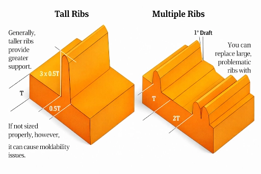
Rib Height, Aspect Ratio, and Buckling Risk

Rib height is often increased to improve stiffness, but in injection molding rib design, taller ribs do not always translate into better performance. Beyond a certain point, increasing rib height introduces molding, structural, and ejection risks that outweigh the stiffness benefit.
In practice, rib height must be evaluated together with rib thickness and material behavior. A rib that is too tall relative to its thickness becomes unstable and difficult to manufacture consistently.
How Rib Height Influences Stiffness
Increasing rib height increases the effective depth of the section, which improves bending stiffness. This is why ribs are commonly added to thin-wall parts that fail deflection requirements.
However, the stiffness gain from rib height follows diminishing returns. Once the rib reaches a certain height, additional material adds very little stiffness but significantly increases molding risk. Effective rib design injection molding focuses on optimal height, not maximum height.
Aspect Ratio and Buckling Risk in Ribs
The aspect ratio of a rib is defined by the ratio of rib height to rib thickness. High-aspect-ratio ribs behave like slender columns and are prone to buckling under compressive or bending loads.
In real-world applications, this can cause localized deformation even when the overall part appears stiff. Buckling is especially common in ribs used to support bosses or long unsupported spans.
Maintaining a controlled aspect ratio is critical for ensuring ribs remain structurally effective throughout the part’s service life.
Manufacturing Impact of Excessive Rib Height
Tall ribs create narrow flow channels at their base, which increases shear stress during filling. This raises the likelihood of hesitation flow, incomplete filling, and internal stress buildup.
From a tooling perspective, tall ribs also increase ejection force. Insufficient draft combined with excessive rib height often leads to drag marks or rib damage during demolding.
These manufacturing challenges make rib height one of the most DFM-sensitive parameters in injection molding rib design
Practical Guidance on Rib Height
| Rib Height Condition | Common Outcome |
|---|---|
| Too short | Limited stiffness improvement |
| Too tall | Buckling, flow issues, ejection problems |
| Optimized | Stable stiffness and reliable molding |
Rather than relying on a single tall rib, distributing stiffness across multiple moderate-height ribs often produces better structural performance with lower manufacturing risk.
Boss cracking or thread strip-out during assembly?
Share your CAD files and validate boss design before production.
Rib Base Design: Fillets, Radii, and Stress Control
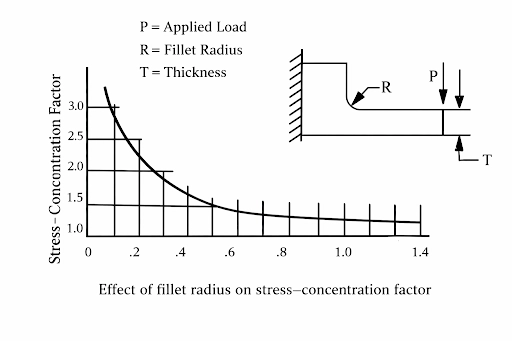
The base of a rib is one of the most critical areas in injection molding rib design. This is where mechanical stress, thermal gradients, and material flow effects intersect. Even well-proportioned ribs can fail if the rib base is poorly designed.
Sharp corners at the rib base create stress concentration points. Under load, these areas become crack initiation zones, especially in brittle or glass-filled plastics. Over time, this leads to fatigue failure or visible cracking, even when the rib itself appears structurally sound.
Adding a fillet at the rib base smooths the transition between the rib and the nominal wall. This reduces stress concentration and allows loads to spread more evenly into the surrounding structure. At the same time, controlled fillets improve polymer flow into the rib and reduce air entrapment during filling.
However, fillet size must be balanced carefully. Excessively large radii increase local wall thickness at the rib root, which can reintroduce sink marks and cooling imbalance. Effective rib design injection molding treats fillets as both a structural and thermal control feature, not just a cosmetic detail.
Draft Angle Optimization for Ribs in Injection Molding
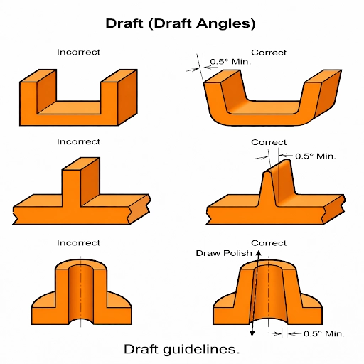
Draft angles are essential for ensuring smooth ejection of ribbed parts from the mold. In injection molding rib design, insufficient draft is a common cause of drag marks, rib damage, and high ejection forces.
As rib height increases, surface contact between the rib and mold steel also increases. Without adequate draft, friction during ejection rises sharply. This not only damages ribs but also accelerates mold wear and increases cycle time due to slower, more cautious ejection.
Material behavior plays a major role in draft requirements. Low-shrink materials generally require more draft to release cleanly from the mold, while higher-shrink materials can tolerate slightly lower draft angles. Surface finish further influences draft needs, as textured ribs demand additional draft to overcome increased friction.
Draft angle optimization in rib design injection molding is therefore a balance between part geometry, material selection, and surface requirements. Well-designed draft angles protect rib integrity, improve cycle stability, and reduce long-term tooling maintenance.
Advanced Boss Wall Thickness Design
Boss wall thickness is one of the most sensitive parameters in injection molding boss design. Unlike ribs, bosses concentrate load and retain heat, which makes thick boss walls a frequent cause of sink marks, voids, and post-mold distortion.
In practice, solid bosses are rarely ideal. A solid boss behaves like a thick wall section, cooling slowly and shrinking unevenly. This often creates sink marks on nearby cosmetic surfaces and increases internal stress. Hollow boss structures are therefore preferred because they reduce mass while maintaining functional strength.
The objective of advanced injection molding boss design is to provide enough wall thickness for screw retention or insert holding without creating thermal imbalance. When wall thickness is excessive, packing pressure cannot compensate for shrinkage at the boss core, leading to cosmetic and structural issues.
Material choice further affects acceptable boss wall thickness. Amorphous materials tolerate slightly thicker walls, while semi-crystalline and glass-filled plastics amplify shrinkage around bosses. In these cases, reducing boss wall thickness and relying on rib reinforcement produces more reliable results than adding material.
Not sure if your rib and boss design will pass tooling or production?
Get a DFM-driven injection molding review from Manufyn before you cut steel.
Boss Height, Diameter, and Collapse Prevention
Boss height and diameter must be balanced carefully to prevent collapse during assembly. Tall, slender bosses are particularly vulnerable to ovalization and cracking when screws are inserted, even if wall thickness appears adequate.
Boss stability is influenced by its slenderness ratio, which relates height to diameter. As boss height increases without a corresponding increase in diameter or reinforcement, resistance to radial expansion decreases. This often results in cracking at the boss base or permanent deformation after screw installation.
Torque transmission is another critical factor. Bosses designed for higher torque loads require sufficient diameter and controlled height to prevent stripping or collapse. Simply increasing wall thickness does not solve this problem and frequently introduces sink and cooling issues instead.
Effective injection molding boss design controls height, diameter, and reinforcement together. Shorter, wider bosses reinforced with ribs distribute loads more evenly and maintain dimensional stability during assembly and long-term use.
Reinforcing Bosses with Ribs: Integrated Design Strategy
Reinforcing bosses with ribs is one of the most effective ways to improve strength without increasing boss wall thickness. In injection molding boss design, ribs help distribute assembly loads away from the boss base and into the surrounding wall structure, reducing stress concentration and improving long-term durability.
When bosses are left unsupported, the entire assembly load is concentrated at the boss root. This commonly leads to cracking during screw insertion or creep deformation over time. By adding ribs, loads are shared across a larger area, lowering peak stress and improving resistance to pull-out and strip-out.
However, rib-to-boss integration must be done carefully. Ribs attached at sharp angles or merged abruptly into the boss can create new stress traps. Smooth transitions and controlled rib geometry allow forces to flow gradually from the boss into the part body, improving both strength and moldability.
From a manufacturing standpoint, rib-reinforced bosses also cool more evenly than thick, unsupported bosses. This reduces sink marks, improves dimensional stability, and lowers the risk of tooling changes after trials. For this reason, reinforcing bosses with ribs is a preferred strategy in production-ready injection molded parts.
Working on a plastic part with ribs or bosses?
A quick DFM review can catch sink marks, warpage, and boss failures before tooling.
Material Selection Impact on Rib & Boss Design
Material behavior has a significant influence on how ribs and bosses perform in injection molding. A rib or boss geometry that works well in one material may fail when the resin is changed, making material-specific design considerations essential.
Amorphous plastics typically shrink more uniformly, which allows slightly more flexibility in rib and boss geometry. Semi-crystalline plastics, on the other hand, shrink more aggressively and unevenly, increasing the risk of sink marks, warpage, and stress buildup around ribs and bosses.
Glass-filled materials introduce additional complexity due to anisotropic shrinkage. Fiber orientation restricts shrinkage in one direction while amplifying it in another, which can cause ovalization of bosses and stress concentration at rib roots. In such materials, conservative rib thickness and well-distributed reinforcement are more effective than adding mass.
Because of these variations, rib design injection molding and injection molding boss design must always be validated against the selected material early in the DFM process. Aligning geometry with material behavior reduces surprises during tooling and improves production consistency.
Material choice affects rib and boss performance
Manufyn helps align material selection with part geometry.
Mold Flow Behavior Around Ribs and Bosses
Ribs and bosses have a direct influence on how molten plastic flows inside the mold. Because these features interrupt the main flow front, they often become the source of hesitation, air entrapment, and weld lines if not designed carefully.
At rib roots, flow can slow down as the melt splits and rejoins. This hesitation increases the risk of short shots in thin ribs and weak knit lines near the rib base. Similarly, bosses force the flow to divide and wrap around a core, which commonly results in weld lines forming behind the boss. These weld lines may be cosmetic issues or structural weak points, depending on part function.
Air entrapment is another frequent issue. Poorly vented ribs and deep boss pockets trap air as the melt advances, leading to burn marks or incomplete filling. From a design perspective, smoother transitions, controlled rib thickness, and proper boss placement help maintain consistent flow and reduce these risks.
Effective rib design injection molding and injection molding boss design always consider flow behavior early, often supported by mold flow analysis during DFM. This allows potential filling issues to be identified before tooling begins.
Not sure if this design will mold cleanly?
Get an injection molding DFM review before you move to tooling.
Cooling and Warpage Control for Ribbed Parts
Cooling behavior is one of the primary reasons ribs and bosses cause warpage in injection molded parts. Ribs and bosses retain heat longer than surrounding walls, which creates differential cooling and uneven shrinkage during solidification.
When ribs cool more slowly, the surrounding wall shrinks first and pulls material inward. This often results in sink marks, surface distortion, or overall part warpage. Bosses amplify this effect because of their mass and depth, especially when located near cosmetic surfaces.
Controlling warpage starts with geometry. Balanced rib thickness, moderate rib height, and hollow boss structures reduce heat concentration. Proper spacing between ribs allows heat to dissipate more evenly, improving dimensional stability after ejection.
From a tooling perspective, cooling channel placement plays a major role. Cooling lines positioned close to rib and boss regions help equalize temperature across the part. When geometry and cooling design work together, ribbed parts achieve better flatness, tighter tolerances, and more predictable production behavior.
Ejection Challenges in Rib & Boss-Heavy Injection Molded Parts
Parts with dense rib networks and multiple bosses often face ejection-related challenges during injection molding. Even when ribs and bosses are dimensionally correct, poor consideration of ejection behavior can lead to cosmetic defects, part damage, and increased cycle time.
Ribs increase surface contact with the mold steel, while deep bosses can create vacuum effects. Together, these features significantly raise ejection forces. If ejection is not planned alongside rib and boss design, parts may stick in the mold, deform during ejection, or show visible drag marks.
Common Ejection Challenges in Rib & Boss Design
| Ejection Challenge | Why It Happens | Impact on Production |
|---|---|---|
| High ejection force | Tall ribs and deep bosses increase steel contact | Part damage, slower cycles |
| Drag marks on ribs | Insufficient draft or poor surface finish | Cosmetic rejection |
| Rib breakage | Thin or tall ribs under high ejection load | Scrap and rework |
| Vacuum lock in bosses | Deep blind bosses trap air | Incomplete ejection |
| Uneven ejection | Poor ejector pin placement near ribs/bosses | Part distortion |
Effective injection molding rib design and injection molding boss design must account for ejection early. Adequate draft, balanced rib height, venting of deep bosses, and proper ejector pin layout are all critical to stable, repeatable ejection.
Common Rib Design Challenges and Their Root Causes
Ribs are intended to improve stiffness, but when poorly designed, they become a primary source of molding defects. Many rib-related issues do not appear immediately and instead surface during production scaling or long-term use.
The table below summarizes the most common rib design challenges encountered in injection molding and their underlying causes.
Rib Design Challenges Explained
| Rib Design Issue | Root Cause | Why It Occurs |
|---|---|---|
| Sink marks | Rib too thick relative to wall | Slow cooling and shrinkage |
| Cosmetic read-through | Rib placed under visible surface | Differential cooling |
| Warpage | Poor rib placement or spacing | Uneven shrinkage |
| Short ribs | Thin ribs with poor flow | Hesitation during filling |
| Rib cracking | Sharp rib base or high stress | Stress concentration |
| Dimensional instability | Dense rib network | Heat buildup and residual stress |
These challenges highlight why rib design injection molding cannot rely on thickness rules alone. Rib orientation, spacing, base geometry, and interaction with bosses all influence whether ribs improve or degrade part quality.
Common Boss Design Challenges and Their Root Causes
Bosses are among the most failure-prone features in injection molded parts because they carry localized loads during assembly and service. Many boss-related issues appear only after screw insertion, thermal cycling, or prolonged use, making them costly to fix once tooling is finalized.
The table below outlines the most common injection molding boss design challenges, their root causes, and why they occur in production.
Boss Design Challenges Explained
| Boss Design Issue | Root Cause | Why It Occurs |
|---|---|---|
| Boss cracking | Thin wall or sharp boss base | High radial stress during screw insertion |
| Thread strip-out | Insufficient wall thickness or height | Inadequate material to carry torque |
| Boss collapse | High slenderness ratio | Ovalization under assembly load |
| Sink marks around bosses | Solid or thick boss structure | Slow cooling and shrinkage |
| Stress whitening | Localized yielding | Excessive assembly force |
| Dimensional instability | Poor reinforcement | Long-term creep under load |
These challenges explain why injection molding boss design should avoid solid bosses and instead rely on optimized wall thickness combined with rib reinforcement. Treating bosses as isolated features almost always leads to post-assembly failures.
Ribs and bosses often cause tooling changes later.
Manufyn reviews rib and boss geometry early to avoid rework.
Design for Manufacturability (DFM) Checklist for Ribs & Bosses
Design for Manufacturability is where rib and boss design decisions are validated before tooling begins. A structured DFM review helps identify geometry-related risks early, reducing trial iterations, tooling rework, and production delays.
The checklist below highlights the key DFM considerations for ribs and bosses in injection molded parts.
Rib & Boss DFM Checklist
| DFM Checkpoint | What to Validate | Why It Matters |
|---|---|---|
| Rib thickness | Relative to nominal wall | Prevents sink and voids |
| Rib height & spacing | Aspect ratio and layout | Controls buckling and warpage |
| Rib base fillets | Smooth transitions | Reduces stress concentration |
| Boss wall thickness | Hollow vs solid | Improves cooling and strength |
| Boss height & diameter | Slenderness ratio | Prevents collapse |
| Rib-to-boss reinforcement | Load sharing | Improves durability |
| Draft angles | Ribs and bosses | Ensures clean ejection |
| Material behavior | Shrinkage and creep | Avoids dimensional drift |
| Mold flow validation | Flow, weld lines, air traps | Prevents filling defects |
When ribs and bosses pass this DFM checklist, parts are far more likely to mold correctly on the first tool trial and remain stable during production scaling.
Moving from design to production injection molding?
Manufyn helps make your part production-ready.
Rib & Boss Design Validation Using Simulation
Simulation plays a critical role in validating rib and boss design before tooling begins. While basic guidelines help avoid obvious mistakes, simulation reveals how ribs and bosses actually behave during filling, packing, cooling, and ejection.
Mold flow analysis is commonly used to study how molten plastic flows around ribs and bosses. It helps identify hesitation zones near rib roots, weld line formation behind bosses, and air entrapment in deep features. These issues are difficult to predict from CAD alone but become clear through simulation.
Simulation is also valuable for evaluating cooling balance. Ribs and bosses retain heat differently than surrounding walls, which can cause warpage and sink marks. Cooling simulations highlight hot spots and allow designers to adjust geometry or cooling layout before steel is cut.
For structurally critical parts, finite element analysis (FEA) is often used alongside mold flow. FEA evaluates how ribs improve stiffness, how bosses carry assembly loads, and where stress concentration may lead to cracking or creep. When used early, simulation reduces tooling iterations and increases first-time-right production.
Industry-Specific Rib & Boss Design Examples
Rib and boss design requirements change significantly by industry due to differences in load conditions, appearance standards, assembly methods, and service life. The table below clearly outlines how rib design injection molding and injection molding boss design priorities vary across major industries.
Rib & Boss Design Comparison by Industry
| Industry | Rib Design Priorities | Boss Design Priorities | Key Design Challenges |
|---|---|---|---|
| Automotive Components | Ribs are used to increase stiffness, control vibration, and reduce panel flex while maintaining thin wall sections. Rib placement must avoid cosmetic read-through on Class-A surfaces. | Bosses are designed for repeated assembly, thermal cycling, and long service life. Heavy rib reinforcement is commonly used around fastener bosses. | Avoiding sink marks on visible surfaces, managing thermal expansion, preventing long-term creep and cracking. |
| Consumer Electronics Housings | Rib design injection molding focuses on stiffness in very thin walls. Ribs are shallow, closely controlled, and carefully spaced to protect external aesthetics. | Injection molding bosses are compact and thin-walled due to space constraints. Bosses rely heavily on rib reinforcement for screw retention. | Limited space, high cosmetic requirements, sink marks, boss cracking during assembly. |
| Industrial Enclosures | Ribs are larger and more widely spaced to improve rigidity and load-bearing capacity. Cosmetic constraints are minimal compared to structural needs. | Bosses are designed to handle higher torque, heavier fasteners, and long-term static loads. Reinforcement is critical. | Preventing boss collapse, managing long-term creep, ensuring dimensional stability in harsh environments. |
| Electrical Enclosures | Ribs provide stiffness to large flat panels and help control warpage. Rib layout often supports sealing and enclosure integrity. | Bosses support mounting hardware, covers, and internal components. Boss strength and positional accuracy are critical. | Warpage control, maintaining sealing surfaces, material behavior under temperature variation. |
| Medical Device Housings | Ribs are designed to provide stiffness while supporting thin, lightweight designs. Clean geometry is required for tooling precision. | Bosses must withstand controlled assembly loads without cracking. Designs often prioritize consistency and repeatability. | Tight tolerances, material sensitivity, avoiding stress whitening and micro-cracks. |
Why This Industry Comparison Matters
This comparison highlights why rib and boss design cannot follow a single universal rule set. What works for an industrial enclosure may fail in a consumer electronics housing, and automotive parts demand a completely different balance of stiffness, durability, and aesthetics.
Effective rib design injection molding and injection molding boss design always adapt geometry, reinforcement strategy, and material selection to the specific industry application to ensure both performance and manufacturability.
How Manufyn Designs Production-Ready Ribs & Bosses
At Manufyn, rib and boss design is treated as an engineering and manufacturability decision—not a late-stage cosmetic fix. Every rib and boss is evaluated in the context of part function, material behavior, tooling constraints, and production volume.
During the DFM stage, rib design injection molding parameters such as thickness, height, spacing, base fillets, and draft are reviewed to balance stiffness with cooling stability. Injection molding boss design is validated for wall thickness, height-to-diameter ratio, reinforcement strategy, and long-term load behavior.
For complex or high-risk parts, mold flow and structural simulation are used to validate filling, cooling, and stress distribution before tooling begins. This approach reduces trial iterations, avoids tooling rework, and ensures consistent performance during production scaling.
The result is rib and boss geometry that molds cleanly, assembles reliably, and performs consistently throughout the product lifecycle.
FAQs: Rib & Boss Design in Injection Molding
Why do ribs still cause sink marks even at 50% thickness?
Rib thickness alone does not determine whether sink marks will occur. Even when ribs follow the 40–60% guideline, sink marks can appear due to excessive rib height, large base fillets, tight rib spacing, or uneven cooling. Material shrinkage behavior and cooling channel placement also play a major role. This is why rib design injection molding must consider geometry and thermal balance together.
Can ribs fully replace thick walls for strength?
In most injection molded parts, ribs are far more effective than thick walls for improving stiffness. Ribs increase bending resistance by shifting the neutral axis without increasing mass. Thick walls, on the other hand, introduce cooling problems, sink marks, and longer cycle times without proportional strength benefits.
Why do injection molding bosses crack during screw insertion?
Boss cracking is usually caused by stress concentration at the boss base during radial expansion. Thin boss walls, excessive boss height, sharp transitions, or lack of rib reinforcement increase the risk of cracking. Poor injection molding boss design concentrates load instead of distributing it into surrounding walls.
How do glass-filled plastics affect rib and boss design?
Glass-filled plastics shrink anisotropically, which amplifies stress at rib roots and boss bases. Fibers restrict shrinkage in one direction while increasing it in another, leading to cracking, ovalization, or dimensional instability. Conservative rib thickness, controlled boss geometry, and proper reinforcement are essential when using glass-filled materials.
Should bosses be placed under cosmetic surfaces?
Ideally, bosses should not be placed directly under cosmetic or Class-A surfaces. Bosses retain heat and increase the likelihood of sink marks and surface distortion. When unavoidable, bosses must be isolated using spacing, thinner walls, and rib reinforcement to protect surface appearance.
Is mold flow analysis necessary for rib and boss design?
Mold flow analysis is highly recommended for complex parts, large rib networks, or tight tolerance applications. It helps identify hesitation flow, weld lines, air traps, and cooling imbalance that are difficult to predict from CAD alone. Early simulation significantly reduces tooling changes and production risk.
Not sure if your rib and boss design will pass tooling or production?
Share your CAD files and get a DFM-driven injection molding review from Manufyn.