Manufyn reviews part design before injection molding begins.
If you’re searching for design guidelines for injection molding before cutting tooling, this guide will show you how to engineer parts that mold cleanly, cool evenly, eject without damage, and assemble without distortion. Most molding failures happen in CAD — not on the press — which is why injection molding design must be resolved before steel is cut.
Injection molding is not just 3D modeling. It is engineered around:
- Flow behavior → how resin fills geometry without hesitation or weld lines
- Cooling balance → how shrinking occurs without warpage or internal stress
- Draft direction → how the part releases from the mold without damage
- Thickness control → how to prevent sink, voids, and short shots
- Parting line strategy → how the tool opens, shuts off, clamps & ejects
This injection molding design guide explains the rules that protect projects from redesign loops, tool rework, defect-driven scrap, and OEM rejections. If a part isn’t moldable, it isn’t manufacturable, no matter how good the CAD looks.
We design for moldability before cost, cost before tooling, and tooling before production — not the other way around.
What this guide will help you avoid
- Sink marks & burn spots
- Flashing & ejector drag scars
- Knit lines at functional surfaces
- Warp from cooling imbalance
- Threads that can’t demold
- Incorrect tolerance expectations

Wall Thickness: The First Rule of Moldability
Wall thickness determines flow, cooling, shrinkage, and cost. The resin must travel through consistent thickness to fill without hesitation or uneven cooling. Violating thickness rules is the root cause of 80% of molding defects.
Recommended Wall Thickness (By Material)
| Material | Recommended Wall Range | Why It Matters |
|---|---|---|
| ABS | 1.2–2.8 mm | Rigid, general-purpose, stable cooling |
| PP | 1.2–2.5 mm | Shrink + warp sensitive; avoid bulk zones |
| PC | 1.0–3.0 mm | Holds detail but heat buildup risk |
| PA6/PA66 | 0.7–2.0 mm | Semi-crystalline → shrink & warp control |
| POM/Delrin | 0.8–2.5 mm | Good flow, needs core-outs for thickness |
Thickness Transition Rules
- Keep internal mass low → rib, don’t bulk up
- Reduce thickness from inside → core-out, don’t stack plastic
- Add radii to transitions → avoid stress concentration
- Increase thickness in steps, never sudden jumps
- Don’t exceed 3× nominal wall unless structurally unavoidable
If wall thickness is wrong, the mold will fail no matter who manufactures it.
This rule sits at the core of design guidelines for injection molding because thickness defines flow and cooling before tooling is built.
Before tooling is quoted, let us check thickness strategy.
Draft Angles: Design for Ejection, Not Just Geometry
Draft is the exit path of the plastic part. Without draft, the part scrapes steel during ejection, creating drag marks, scars, and long-term tool wear. Many projects fail because designers model vertical walls with zero draft — a geometry that cannot physically demold.
Draft Angle Requirements
| Surface Type | Minimum Draft | Application Notes |
|---|---|---|
| Smooth/Glossy Surfaces | 0.5°–1° | Only on non-cosmetic faces |
| Light Texture / Matte | 1°–2° | Most general consumer products |
| Deep Texture / Grain / Leather | 3°–5° | Texture depth needs escape angle |
| Vertical Ribs / Bosses | 0.5°–0.75° per side | Prevents drag + injection streaks |
Design Rules That Prevent Ejection Failure
- Every vertical wall gets draft — no exceptions
- Textured faces need more draft, not less
- Draft both sides of shutoffs & core steel
- Add draft to clips, snaps & living hinges for fatigue life
- Where draft is impossible → we plan lifters/sliders, not mistakes
Zero draft is not a design decision — it’s a manufacturing problem waiting to happen.
This step is essential for designing for injection molding because demold friction defines cosmetic outcome and tooling life.
Ribs, Bosses & Structural Reinforcement (The Strength-Without-Bulk System)
Ribs and bosses are not decorative geometry — they are load pathways, stiffness multipliers, and cooling stabilizers. Designers who treat them like visual features create sink marks, pull voids, cooling gradients, and torque failures. Designers who treat them like structural systems get predictable results.
The Mechanical Reason Ribs Matter
Plastic doesn’t fail from lack of material — it fails from:
- uncontrolled flexing,
- localized stress at sharp transitions,
- internal cooling differentials,
- and unsupported load direction.
Ribs create directional stiffness, meaning they channel force along an intended axis.
| If You Want To… | Design Decision |
|---|---|
| Increase bending resistance | Add rib parallel to force direction |
| Reduce torsion twist | Add triangular gusset ribs |
| Prevent column collapse | Add cross ribs between walls |
| Improve snap fit durability | Add ribs opposite latch engagement |
This is the logic missing in 90% of online advice.
Rib Geometry — Updated, Detailed, Real Numbers
| Structural Variable | Recommended Range | Why |
|---|---|---|
| Rib Thickness | 35–60% of parent wall | Prevents sink from differential cooling |
| Rib Height | 2.5–3× wall | More → causes flex & warpage |
| Draft | 0.5–1˚ per side | Reduces breakout, drag, ejector stress |
| Root Fillet | 0.25–0.5× wall | Eliminates crack initiation points |
| Spacing | ≥2× rib thickness | Prevents thermal imbalance & print-through |
If your rib design exceeds height without support, it becomes a tuning fork — not a reinforcement.
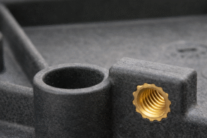
Boss Engineering — Not Just Cylindrical Decorations
Bosses need to survive:
- torque load during fastening,
- hoop stress during thread insertion,
- and thermal deflection during cooled ejection.
Boss Design Ratios
| Variable | Specification |
|---|---|
| Outer diameter | 2× screw diameter (min) |
| Boss wall thickness | 60% of parent wall |
| Insert press fit interference | 0.05–0.2mm depending on resin |
| Support ribs | Required for tall bosses & inserts |
| Insert depth | ≥ 1.2× insert OD |
Prevent This
- Thick boss = sink
- Unsupported boss = cracks at base
- Blind boss + heat insert = split failure
- Sharps at root = crack propagation
Do This
- Rib-supported → stiffness without bulk
- Core-out interior → no heat bubble collapse
- Add relief for thread entry → clean start path
- Add draft on internal cylinder → exit safety
This is critical to design guidelines for injection molding because reinforcement must be structural, not volumetric.
Not sure if your support system will fail under load or cooling?
Section 4 — Gate Placement, Flow Engineering & Weld Line Control (The Flow Physics Layer)
Gate placement decides if a part fills cleanly or fails expensively. Before CAD aesthetics, before cosmetic considerations, the part must be designed for flow velocity, fill pressure, shear rate, cooling gradient, and weld-line formation.
Gating Controls the Four Core Forces
| Variable Gate Controls | Impact |
|---|---|
| Flow front velocity | Weld line formation |
| Pack pressure | Dimensional stability |
| Shear stress | Surface finish + burn marks |
| Cooling timing | Warp, internal stress, and sink |
When gate location is wrong, you don’t fix the mold — you fight physics.
Gate Placement Decision Matrix
| Part Type | Best Gate | Why |
|---|---|---|
| Cosmetic housings | Valve/Hot Tip | No vestige, uniform fill, fewer weld lines |
| Thin-walled parts | Fan Gate | Spreads flow, reduces hesitation |
| Long flow paths | Dual Gate (balanced runner) | Prevents flow freeze-off |
| Structural load areas | Edge/Submarine | Moves weld line out of stress zone |
| High clarity plastics (PC/PMMA) | Hot Runner | Heat memory, reduced shear whitening |
Never gate into a cosmetic face, load-bearing feature, or alignment/datum surface.
Weld Line & Knit Line Prevention Framework
Most guides say “avoid weld lines.”
This guide says how to engineer them out.
Flow Alignment Rules
- Move weld lines into low-load zones
- Reinforce weld-line-adjacent geometry
- Add round transitions to prevent flow collision
- Increase thickness where flow fronts meet
- Increase gate size (slightly) if flow stalls
If Weld Lines Are Unavoidable
- Change flow direction, not just volume
- Add a second gate but balance pressure
- Shift the knit line away from functional geometry
These decisions define designing for injection molding — not just modeling for visuals.
Parting Line, Shutoffs & Ejection Direction (The Mold Reality Layer)
Injection molding is not just “splitting the part.” It is engineering where the mold agrees to separate so geometry, draft, undercuts, and ejector direction all make sense in a real steel tool. Most designs fail because the parting line is reactive (decided after CAD) instead of architected.
The Parting Line is a Tooling Decision — Not a CAD Consequence
A part designed without a defined parting line forces the mold maker to:
- add draft you never accounted for,
- relocate features you didn’t approve,
- or reject geometry that physically cannot open.
When the parting line is wrong:
- flash appears along cosmetic edges
- shutoffs leak → razor-edge defects
- cosmetic faces get ejection marks
- actions are required (extra cost) just to demold a simple shape
When the parting line is right:
- tooling becomes simpler
- ejector paths are predictable
- cost drops (fewer actions, lifters, sliders)
- cosmetic surfaces stay clean
The parting line is the boundary between design and tooling reality.
Parting Line Selection Rules (Steel Reality, Not CAD Theory)
| If Your Part Has… | Best Parting Line Choice | Why |
|---|---|---|
| Flat faces | Single planar split | Clean eject, simple shutoffs |
| Deep geometry | Contoured split | Avoids “biting” into steel |
| Cosmetic surfaces up top | Backside parting line | Protect visible faces |
| Undercuts | Split + lifter/slide | Access to trapped geometry |
| Internal latch/Snap | Z-split | Release without scraping |
This rule set sits at the heart of any injection mold design guide because parting line choice defines how steel moves, opens, releases, and cools.
Shutoffs & Steel-on-Steel Reality
Shutoffs must be designed with:
- 3°–7° minimum shutoff angle (depending on resin)
- positive locking geometry (not parallel faces)
- pressure direction support (shutoff against force, not with it)
Parallel shutoffs = flash factories.
Angled shutoffs = predictable performance.
Ejection Direction = Draft Direction
You can’t draft north and eject south.
Ejection decisions must be:
- aligned with draft direction,
- aligned with parting line,
- aligned with functional surfaces,
- not passing through cosmetic faces.
If ejection marks appear on visible faces, the designer — not the mold — failed.
Sink, Warp, Flash, Short Shots & Cooling: Root Cause → Fix
Most designers only ask: “How do we remove this defect?”
We ask: “Why did the geometry instruct the defect to exist?”
Every molding defect is a message from the part telling you which rule you broke.
Sink Marks — The Thickness Crime
Root Cause: Excess material at local geometry → cooling delta
Design Fix:
- reduce wall thickness
- core out hidden volume
- rib support instead of bulk mass
- move thickness to non-cosmetic zone
Warping — The Internal Stress Battle
Root Cause: Cooling imbalance + resin shrink gradient
Design Fix:
- Symmetrical wall sections
- Gate placement near thicker mass
- Material choice → semi-crystalline warps more
- Equal cooling channel routing
Warp isn’t random — it’s a temperature map.
Flash — Steel Seal Failure
Root Cause: Poor shutoff angle + mold face mismatch
Design Fix:
- 3°+ shutoff angle
- Add draft to trap geometry away from parting line
- Remove parallel steel faces
- Reinforce alignment with keys/pins
Flash is not a press setting problem — it’s a geometry problem created in CAD.
Short Shots — Starved Flow Front
Root Cause: Thin-to-thick transitions kill pressure
Design Fix:
- Move gate closer to final fill point
- Widen thin sections at flow convergence
- Increase venting near end-of-fill zones
- Rib substitution instead of bulk mass
Short shot = flow starvation. Fix the runway, not the pressure.
Cooling → The Defect You Can’t See in CAD
Cooling determines:
- dimensional stability
- tolerance retention
- internal stress
- cycle time (cost driver)
- warpage direction
If cooling is wrong, every defect is “correct behavior from the part.”
These failure modes are why designing for injection molding requires thickness, gating, draft, and cooling to be coordinated — not isolated.
If your parts have sink, warp, flash or weld lines, stop guessing. Upload CAD for Manufyn’s Moldability Defect Analysis
Material Behavior, Resin Shrinkage & Tolerance Reality
Injection molding failures are rarely machine problems — they are material behavior problems caused by designing plastic parts like machined metal components. Plastics don’t behave like metals. They shrink, flex, absorb moisture, equalize stress slowly, and take the shape of the temperature gradient, not the CAD model.
To design correctly, every material decision must answer 4 questions:
- How does it flow? (viscosity & shear sensitivity)
- How does it cool? (shrinkage & crystallinity)
- How does it behave structurally? (modulus, fatigue, impact resistance)
- How does it age? (UV, heat, chemical exposure, creep)
Amorphous vs Semi-Crystalline — The Behavior That Decides Tolerances
| Property | Amorphous (ABS/PC/PMMA) | Semi-Crystalline (PA66/PP/POM) |
|---|---|---|
| Flow | Predictable | Directional (fiber alignment) |
| Cooling | Even | Uneven → internal stress pockets |
| Shrinkage | Low (0.4–0.7%) | High (1.2–2.5% or more) |
| Tolerance Stability | Better | Depends heavily on cooling balance |
| Warpage Risk | Low | High if cooling not symmetrical |
Design translation:
- If you need dimensional stability → choose amorphous
- If you need strength & chemical resistance → choose semi-crystalline
- If you need both → design for shrink first, tolerance second
Never tolerance plastics like CNC parts.
You don’t “hold tolerance,” you design tolerance bandwidth that the resin can realistically achieve.
Realistic Tolerance Ranges for Molded Parts
| Feature Type | Practical Tolerance | Why |
|---|---|---|
| Uncritical faces | ±0.25–0.50mm | Standard cooling variation |
| Alignment features | ±0.10–0.25mm | Requires consistent gate/cooling |
| Snap fits / latches | ±0.05–0.15mm | Flex tolerance; design for compression |
| Critical assemblies | ±0.03–0.08mm | Needs post-processing or stable resin |
| Optical/precision parts | ±0.02mm+ (with inserts/grind) | Mold steel dictates limits |
If a designer calls ±0.01mm on molded plastic, they are not designing — they are hoping.
CTE (Thermal Expansion) Must Be Designed Around
Plastic expands when heated, shrinks when cooled, and continues to move even after ejection.
- Short cooling time = shape memory + warp
- Excess cooling = cycle time cost + stress locking
- Moisture absorption = dimensional drift (nylon!)
Unmanaged CTE is why parts fit on Monday, bind on Friday.
Undercuts, Lifters, Slides, Cores & When They’re Worth the Cost
Undercuts are where design ambition meets tooling reality. They are not “bad,” but every undercut must be intentional and justified by value. The question is not “Can we mold it?” — it’s “Should we mold it this way?”
The Four Types of Undercuts
| Undercut Type | Tooling Solution | When to Use It |
|---|---|---|
| Internal Undercut | Collapsible core | Cylindrical ID features with no straight extraction path |
| External Undercut | Slide / cam action | External latch or profile that traps steel |
| Hook / Snap Undercut | Lifter | Flexible features requiring angled release |
| Through-Part Undercut | Split cavity | Geometry that crosses parting line |
Cost Reality:
Undercuts increase:
- cycle time,
- mold cost,
- maintenance intervals,
- tooling complexity,
- defect sensitivity.
Only keep an undercut if it performs a functional purpose: latch, seal, alignment, load transfer, assembly reduction.
Lifters vs Slides vs Collapsible Cores
| Solution | Cost | Reliability | Purpose |
|---|---|---|---|
| Lifter | $$ | Medium | Angled release for snap fits, hooks, tabs |
| Slide | $$$ | High | Precise external geometric undercuts |
| Collapsible Core | $$$$ | High | Internal cylindrical undercuts / threads |
| Hand-load Inserts | $ | Low | Prototype/low volume to avoid complex tooling |
If volume < 2,000 units → consider hand-loaded inserts to delay capital spend.
If volume > 20,000 units → automate (slide/lifter/core) to reduce per-part cost.
When to Remove Undercuts Entirely
Remove undercuts if:
- They exist only for aesthetics
- A snap fit can be redesigned for vertical release
- Assembly can be re-sequenced to avoid interference
- Draft, not action, solves the geometry trap
Don’t spend $4,000 on a lifter to solve a $0.40 geometry mistake.
Not sure if your undercut needs a lifter, slide, or redesign? Get Undercut/Action Cost Justification Review
Snap Fits, Living Hinges & Flexible Features (Functional Plastics Engineering)
Snap fits and living hinges are where mechanical function meets polymer physics. These features are not “just geometry” — they are stress systems. The moment a snap fit engages or a hinge flexes, the design is tested against modulus, strain, creep, deformation, fatigue, and recovery.
A snap that fails wasn’t over-stressed — it was under-designed.
Snap Fit Design Rules (Actual Engineering, Not Guessing)
Snap Engagement Checklist
| Parameter | Design Target | Why It Matters |
|---|---|---|
| Interference | 0.25–0.60mm depending on resin | Controls retention force without cracking |
| Engagement Angle | 10°–30° ramp | Reduces insertion force; avoids stress peak |
| Underhook | 0.4–0.6mm | Prevents disengagement under vibration |
| Fillet Radius | 0.5–0.75mm | Eliminates crack starter points |
| Draft | 0.5°–1° | Allows clean release during molding |
Snap Behavior Must Match Resin Family
| Material | Snap Fit Suitability | Reason |
|---|---|---|
| PP | ⭐⭐⭐⭐⭐ Excellent | High flexural fatigue + low creep |
| PE/LDPE | ⭐⭐⭐⭐ Good | Flexible; watch deformation under heat |
| ABS | ⭐⭐⭐ Decent | Stiff, brittle; needs larger fillets |
| PC | ⭐⭐⭐ Controlled | Strong; avoid stress concentration |
| PA66 (Nylon) | ⭐⭐ Sensitive | Absorbs moisture → tolerance drift |
In snap fits, geometry doesn’t break — stress concentration does.
Living Hinges — The Most Abused Feature in Plastic
A living hinge is a designed bend axis, not just a thin strip of plastic.
Hinge Engineering Requirements
| Variable | Best Practice |
|---|---|
| Hinge Thickness | 0.25–0.45mm (PP only) |
| Radius | 0.75–1.0× hinge thickness |
| Length | 8–12× thickness minimum |
| Support Beads | Yes — opposite side |
| Material | Only PP or PE (PC/ABS crack) |
If you put a hinge in ABS — it will fail.
Not “maybe.” Not “over time.” It will fail.
Hinge Failures Are Predictable:
- Cracks = thickness too high
- White stress lines = radius too small
- Plastic whitening = wrong resin or snap direction
- Deformation = no stress relief bead
Snap Fit / Hinge → Tooling Impact
- More draft needed for latch faces
- Gate location must avoid hinge line
- Cooling channels must be symmetrical
- Ejector pins cannot interrupt flex zones
This is why designing for injection molding must include functional geometry, not just form.
Assembly-First Design & Tolerance Stack Control
Poor molded assemblies don’t happen at assembly — they happen in CAD.
If the part doesn’t align, locate, and load-transfer correctly on screen, it won’t do it after molding.
Injection molding assemblies must be designed assembly-first, not part-first.
Assembly Logic Before Tolerances
Ask these questions before dimensioning:
- What aligns the parts? → locating features
- What locks position? → bosses, pins, snap hooks
- What transfers load? → ribs, walls, gusset
- What controls repeatability? → datum, not edges
- What prevents tolerance fight? → relief zones & clearance
Molded parts don’t meet — they locate.
Tolerance Stack for Plastics (Realistic, Not Theoretical)
A tolerance stack must:
- Accept shrinkage variation
- Consider cooling unbalance
- Account for draft taper influence
- Compensate for material creep over time
Tolerance Strategy Framework
| Alignment Type | Fit Strategy | Why |
|---|---|---|
| Visual alignment | 0.15–0.30mm clearance | Cosmetics hide minor mismatch |
| Functional alignment | 0.05–0.10mm | Required for hardware/fasteners |
| Press fit alignment | Interference 0.05–0.15mm | Prevents slip but avoids cracking |
| Precision alignment | Add datum + post-process | Injection molding alone is insufficient |
If your stack relies on perfect surfaces, you’re not designing — you’re gambling.
Datum Strategy That Prevents Assembly Failure
- Define functional datums, not aesthetic ones
- Base on features that survive molding tolerance shift
- Avoid choosing cosmetic faces as primary datums
- Don’t datum off flexible features (snaps, hinges)
Correct datum design reduces:
- assembly force problems
- cumulative tolerance drift
- misalignment during fastening
squeaks, buzz, rotational play
Surface Finish, Texturing & Tooling Steel Selection (Function, Cosmetics & Wear Map)
Surface finish isn’t “look and feel” — it’s friction behavior, tool wear signature, and release performance. Finish directly affects:
- draft angle requirements
- ejection force
- sealing performance
- scratch resistance
- appearance grading
- tool maintenance cycles
Designing a surface without planning the finish is designing a defect.
SPI Finish Standards (The Reality Chart)
| SPI Grade | Finish | Typical Use Case | Draft Requirement |
|---|---|---|---|
| A-1/A-2 | Polished/Optical | Lenses, display housings | 0.5° minimum |
| B-1/B-2 | Semi-gloss | Consumer casings, panels | 1°–1.5° |
| C-1/C-2 | Satin/Matte | Automotive interiors | 1.5°–2.5° |
| D-1/D-2 | EDM/Texture | Industrial housings | 3°–5° |
| T-series | Grain/Laser texture | Grip zones, touch surfaces | 4°–8° |
Texture adds friction. Friction adds ejection force.
Ejection force adds tooling wear.
Tooling wear adds maintenance cost.
This is why injection molding design must match finish to draft and steel type.
Tooling Steel Selection Based on Finish & Production Run
| Steel | Hardness | Best For | Why It Matters |
|---|---|---|---|
| P20 | Soft (pre-hardened) | Low/mid volume, cosmetic parts | Easy to texture & rework |
| H13 | Hardened | High volume, abrasive resins | Wear resistant, stable finish |
| S7 | Impact-resistant | Slides, lifters, shutoffs | Absorbs shock without deforming |
| 420SS | Corrosion-resistant | Optical & medical | Polish retention + clarity |
Design Translation:
- If you want a textured cosmetic part → P20 + generous draft
- If you want glossy visibility surfaces → 420 SS + tight process control
- If you want lifetime production → H13 and don’t under-draft
Texture Failures & Prevention
- Peel-off / flaking → draft too low for texture depth
- Highlight scars → ejector on cosmetic surface
- White stress marks → no radii at corner transitions
- “Orange peel” → low polish on high-vis surfaces
- Increase draft before adding texture
- Move ejectors away from A-class faces
- Add radii where texture meets gloss transitions
- Pull test sample before steel commitment
Surface decisions are a core part of any injection mold design guide because finish determines not only aesthetics but tooling life and unit cost.
Cooling, Cycle Time & Conformal Cooling (Cost Engineering Layer)
Cooling is the invisible engineering layer that decides the fate of the part.
Not machine brand. Not clamp tonnage. Not press operator skill.
Cooling is cost, warpage, shrinkage, repeatability, and cycle time — all at once.
Cooling Cycle = The Real Cost Per Part
The #1 cost driver in molding is not material.
It’s not labor.
It’s not press time.
It’s cooling duration per shot.
| Steel | Hardness | Best For | Why It Matters |
|---|---|---|---|
| P20 | Soft (pre-hardened) | Low/mid volume, cosmetic parts | Easy to texture & rework |
| H13 | Hardened | High volume, abrasive resins | Wear resistant, stable finish |
| S7 | Impact-resistant | Slides, lifters, shutoffs | Absorbs shock without deforming |
| 420SS | Corrosion-resistant | Optical & medical | Polish retention + clarity |
Most designers overpay for production simply because they never designed for cooling.
Cooling System Architectures
| Method | Best For | Why |
|---|---|---|
| Straight-Line Channels | Standard geometry | Basic heat removal |
| Baffled Channels | Asymmetric walls | Directs coolant to hotspots |
| Spiral / Helical | Round / cylindrical parts | Even temperature gradient |
| Conformal Cooling | Complex 3D shapes | Follows geometry → fastest cycle |
| Micro-Channel Hybrid | High-precision parts | Warpage control + uniform shrink |
Conformal cooling is not a luxury; it’s a cost recovery system.
Thermal Behavior Rules
- Thin walls cool faster → shrink less → warp less
- Thick walls hold heat → sink more → warp more
- Sharp corners concentrate heat → stress cracks later
- Resin behavior dictates cooling time (PC > PP > ABS)
If you don’t design for cooling, warpage isn’t a defect — it’s the expected outcome.
When to Justify Conformal Cooling
Choose conformal cooling when:
- tolerances below 0.10mm are required
- cosmetic surfaces cannot distort
- cycle time reduction will pay back tooling cost
- core geometry traps heat in corners/deep pokets
If annual volume > 50,000 pcs/year → conformal is usually profitable.
If volume < 8,000 pcs/year → stick to baffled/spiral.
This is cost engineering — not cost guessing.
Want to know if traditional or conformal cooling is right for your volume? Request Cooling Configuration & Cycle Time ROI Audit
DFM for Tooling Class, Lifespan & Maintenance (Before Steel, Not After Failure)
DFM isn’t a checklist. It’s a prevention document that ensures the part, mold, material, and production volume are aligned before steel is cut. If DFM isn’t done before tooling, it will be done during rework — which costs 10–40x more.
DFM exists to answer one question:
“Can this part be molded repeatedly without failure?”
Tooling Class Selection Based on Volume
| Tooling Class | Steel | Volume Range | Use Case | When to Choose |
|---|---|---|---|---|
| Class 105 | Aluminum | 100–500 shots | Prototype parts | Early validation / geometry freeze stage |
| Class 104 | P20/Aluminum Hybrid | 500–10,000 shots | Low-volume production | Startups, pre-market validation |
| Class 103 | P20 Steel | 10,000–100,000+ | Mid-volume | Stable parts with minor cosmetics |
| Class 102 | H13 Steel | 100,000–500,000+ | Production | Consumer goods & automotive plastic interiors |
| Class 101 | H13/420SS Hybrid | 500,000–1,000,000+ | Lifetime tooling | Medical, automotive, export-grade, high precision |
Design Decision Logic:
- Cosmetic surfaces → start at Class 103 minimum
- High-wear resins (GF, nylon, PC) → Class 102–101
- Optical/clarity parts → 420SS inserts, not P20
- Moving actions (lifter/slide/core) → no Class 104
If the expected volume fights the tooling class, production will fail instead of parts.
Maintenance Predictors (Design Before Downtime)
The mold should be designed with maintenance built into the geometry:
- Contoured shutoffs that can be stoned cleanly
- Ejectors placed where polish won’t be destroyed
- Gate vestige located for rework allowance
- Textures chosen for predictable refurbishment cycles
If there is no maintenance plan, there is no production plan.
Red Flags That Show a Part Is Not Tool-Ready
- Textured surface + no additional draft
- Vertical walls with zero relief near shutoffs
- Bosses located directly on ejector zones
- Slides needed only because of poor part geometry
- High shrink resin + ornamental cosmetic faces
This is where true injection molding design meets tooling execution — the moment CAD decisions become real steel.
Manufacturing Documentation, Tolerance Data & Release Packages
A design isn’t production-ready until documentation is. Manufacturing fails not because parts are wrong — but because expectations were never aligned between design, production, and QA. Your release package must make the part understandable, repeatable, inspectable, and correctable.
Minimum Documentation for Release
| Document | Purpose |
|---|---|
| 2D Drawing with GD&T | What is being measured? |
| Functional Datum Scheme | Where does assembly locate? |
| Tolerance Stack Table | What range is acceptable? |
| Resin Specification Sheet | What behavior is expected? |
| Gate/Runner/Flow Direction Notes | How will it fill? |
| Draft Callouts | Which direction does geometry release? |
| Critical-to-Function (CTF) Notes | What matters if variation occurs? |
If CTF features aren’t marked, production won’t know what to defend.
GD&T for Molded Parts Must Be Function-Linked
Use GD&T:
- On alignment features
- On sealing faces
- On assembly locators
- On high-load bosses
Do NOT use GD&T:
- On cosmetic faces
- On flexible features
- On thin-walled regions
- On draft-dependent surfaces
Dimensional accuracy means nothing if functional accuracy isn’t protected.
Release Package Validation Steps
- CTF → Identified
- Datum → Assigned to durable geometry
- Tolerances → Matched to resin behavior
- Gate path → Defined & justified
- Cooling zones → Mapped to thick/thin areas
- Draft direction → Confirmed with ejection logic
If all six are green, the mold is ready.
If even one is red, freeze spending — don’t cut steel.
Before you hand files to a toolmaker, let us validate the release. Upload Files for Manufacturing Package Audit with Manufyn
Cost Drivers, Quoting Logic & How to Avoid Overpaying
Injection molding cost is not “material + machine + labor.”
It is the downstream result of choices made in CAD. Most companies get expensive quotes not because suppliers overcharge — but because the part instructs the tool to be expensive.
The 6 Real Cost Drivers (In Order of Impact)
| Cost Driver | Why It Matters |
|---|---|
| Cooling Time | #1 cost multiplier — cycle = cost |
| Tool Complexity | Lifters, slides, cores = higher build + maintenance |
| Surface Finish Class | High polish & textures demand premium steel |
| Material / Resin Choice | Shrink, warp & wear change tool specification |
| Tolerance Ambition | Tight tolerances → slower cycles + post-processing |
| Annual Volume | Dictates tooling class and automation level |
If cooling time goes up 10 seconds, your part price can jump 20–30%.
Where Designers Accidentally Add Cost
- Undercuts that do not serve functional purpose → slides/lifters needed
- Cosmetic faces on A-side where ejectors should be placed → new tool layout
- Zero draft on textured surfaces → mold corrections + rework billing
- Tolerances too tight for resin → post-op machining to save the mold
- Overbuilt walls → extra pack/hold → extended cooling → higher cycle cost
✔ Cost-Engineering Fix
Swap: geometry complexity ➝ feature intent clarity
Swap: slide-required latch ➝ vertical-release snap redesign
Swap: blind boss ➝ relieved path for tooling access
Design determines cost before tooling ever gets quoted.
Pricing Blind Spots to Remove Before RFQ
- Asking for a quote before gate/draft confirmed → inaccurate pricing
- No tooling class specified → vendors assume higher class “for safety”
- No annual volume clarity → can’t scale or choose automation path
- Missing resin callouts → supplier picks wrong shrink basis
If you ask incomplete questions, you get expensive answers.
The Manufyn Cost View
We quote with:
- tooling intent explained
- gating & parting line justification
- cooling logic & cycle target
- resin justification for tolerance
So you see exactly why you’re paying, not just what you’re paying.
Ready to Design for Injection Molding Without Redesign Loops?
Manufyn validates:
- Moldability + geometry feasibility
- Gating + parting line + draft direction logic
- Cooling + shrinkage + cycle cost modeling
- Tolerance stack + assembly-first design
Tooling class selection based on volume
Upload CAD for Free Design-For-Molding Review. Start your Injection Molding DFM Audit with Manufyn
Frequently Asked Questions
What are the key principles of good injection molding design?
Good injection molding design focuses on uniform wall thickness, proper draft angles, gate and runner placement, cooling balance, and realistic tolerance expectations. Following design rules helps parts fill correctly, cool evenly, and eject smoothly — preventing defects like sink, warp, flash, or short shots.
How thick should walls be in injection molded parts?
Wall thickness depends on resin type, but general ranges are 1.2–2.8 mm for ABS, ~1.0 mm for PC, and 0.8–2.5 mm for POM. The goal is consistent thickness to avoid sink marks and differential cooling. This is a core rule in injection molding design to ensure flow and dimensional stability.
Why are draft angles important in injection molding design?
Draft angles allow molded parts to release from the tool without drag or surface damage. Typically, 0.5°–2° minimum draft is recommended depending on surface finish and resin behavior. Lack of draft is one of the most common causes of mold damage and reject parts.
What is the role of ribs and bosses in molded plastic parts?
Ribs provide structural support without adding bulk, while properly sized bosses support fasteners and inserts. Both help reinforce geometry but must follow design guidelines for injection molding to prevent sink marks, stress cracking, and cooling imbalance.
How does gate placement affect the injection molding process?
Gate placement influences how the resin flows, where weld lines form, and how pack pressure develops. Correct gate location prevents hesitation, reduces weld lines in functional zones, and balances fill pressure — critical for both cosmetic and structural integrity.
What causes common injection molding defects like warp, sink, and flash?
- Warp: uneven cooling/shrinkage
- Sink marks: thickness variation / high heat retention
- Flash: poor shutoff geometry or parting line issues
These occur when design choices don’t match material behavior and cooling strategy — a core focus of good injection molding design.
How does resin selection impact part tolerances and shrinkage?
Different resins have different shrink rates (e.g., amorphous vs. semi-crystalline). Material choice affects how much the part will change dimensionally post-cooling. Effective injection mold design must account for shrinkage behavior and tolerance realities of the selected plastic.
What design features increase tooling cost in injection molding?
Undercuts requiring lifters or slides, deep cores needing collapsible cores, complex parting lines, high polish finish requirements, and conformal cooling all add complexity and cost. A strong injection mold design guide helps predict and justify these choices before tooling quotes.