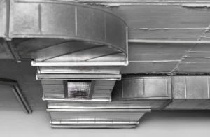
Manufyn reviews ejector pin layout to avoid part damage.
Ejection is the most underestimated phase of injection molding — yet it is where the highest mechanical stress occurs. Once the plastic has cooled and shrunk around the core, the mold must forcibly separate the part from steel. That force is transferred almost entirely through ejector pins.
Poor ejector pin design doesn’t just cause cosmetic defects. It leads to:
- ejector pin marks in injection molding,
- part distortion or cracking,
- sticking and vacuum lock,
- bent or broken pins,
- increased cycle time,
- premature mold maintenance.
In most projects, ejector pins are added after the part geometry is finalized. This is exactly why ejection problems show up during trials instead of being prevented during design.
Ejector pins injection molding is not a tooling detail — it is a design responsibility. Draft angles, wall thickness, texture, material shrinkage, and part geometry all dictate how much force is required to eject a part and where that force can be safely applied.
If ejection isn’t engineered early, it will be “fixed” later — with cost, delays, and compromised surfaces.
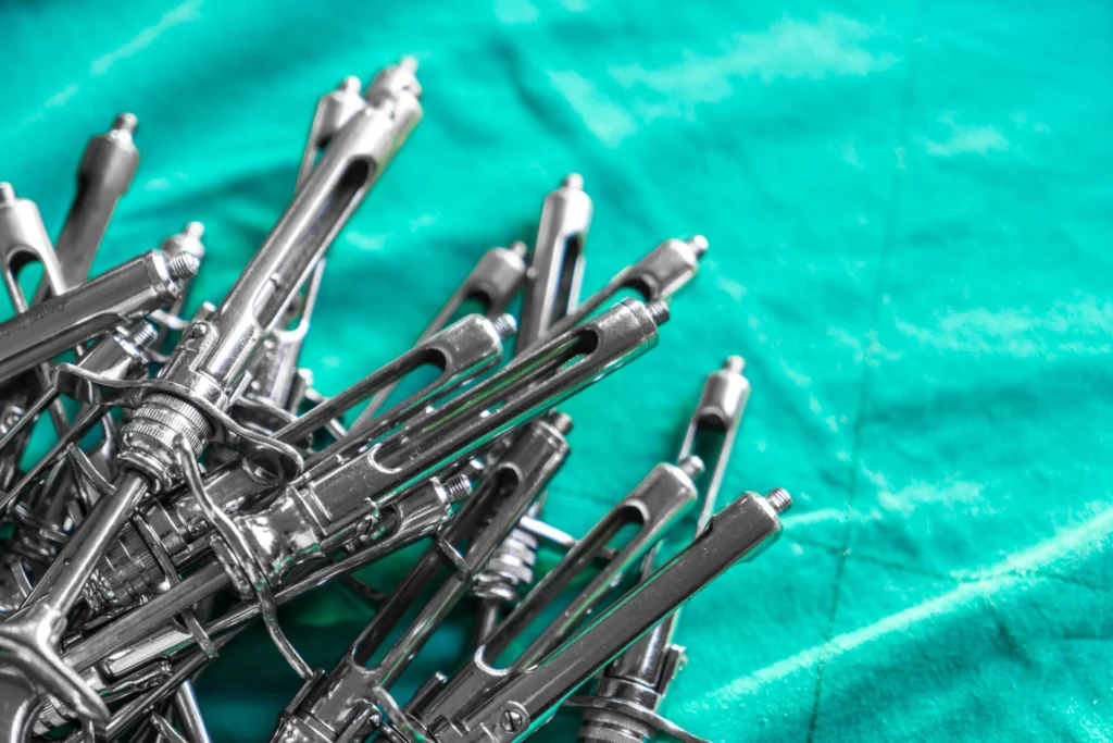
What Are Ejector Pins in Injection Molding?
Ejector pins are hardened steel components used to push a molded plastic part out of the mold once it has cooled and the mold opens. They apply controlled force from the core side of the mold to overcome shrinkage, friction, and vacuum forces.
Ejector pins are precision-guided steel elements driven by an ejector plate system, designed to transmit uniform force to a molded part during ejection without causing deformation or surface damage.
What Ejector Pins Actually Do
- Break adhesion between plastic and steel
- Overcome shrink-fit on the core
- Prevent vacuum lock
- Support controlled, repeatable part release
What Ejector Pins Are NOT
- They are not cosmetic-safe by default
- They are not “invisible” in poor designs
- They do not compensate for lack of draft
- They cannot fix bad part geometry
Most ejector pin marks in injection molding are not pin problems — they are design problems where force is concentrated in the wrong locations.
Check Ejector Pin Risk Zones
If you’re unsure where ejector pins will land or how much force is needed,
Manufyn identifies high-risk ejection zones directly from your CAD.
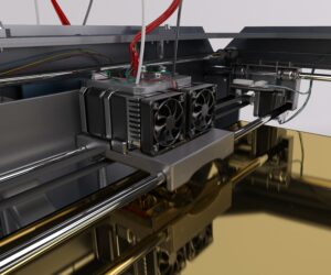
How Injection Molding Ejection Systems Work
Ejection is the most mechanically demanding phase of the injection molding cycle. By the time the mold opens, the plastic part has shrunk tightly around the core, creating friction, adhesion, and often vacuum lock. The ejection system must overcome all three without damaging the part or the tool.
Step-by-Step Ejection Cycle
- Cooling completes → part solidifies and shrinks onto the core
- Mold opens → cavity side retracts
- Ejector system advances → pins/sleeves apply force
- Adhesion breaks → part releases from steel
- Ejector retracts → mold resets for next cycle
Why Parts Stick to the Core Side
Parts almost always remain on the core side, not the cavity side, because:
- The core has more surface contact
- Shrinkage creates interference fit
- Textures increase mechanical grip
- Smooth cores can form vacuum seals
This is why ejector pin placement must always be planned on the core side, aligned with shrink direction and draft.
Ejection Force Is Not Constant
Ejection force increases when:
- Draft angles are insufficient
- Surface texture is applied without added draft
- Cooling time is reduced aggressively
- Wall thickness varies
- Material shrinkage is high
Shorter cycle time = higher ejection force requirement
Designers who optimize cooling without validating ejection often shift defects from “warp” to ejector pin marks in injection molding.
Core Components of an Injection Molding Ejection System
A reliable ejector pin injection molding system is not defined by pins alone. It is a coordinated mechanical assembly where ejector pins, plates, return systems, and supports work together to distribute force evenly and prevent localized stress that leads to ejector pin marks in injection molding.
-
Ejector Pins
Ejector pins are the components that physically push the molded part off the core. They transfer ejection force directly to the plastic and must be placed where the part can safely accept that force. Poor pin placement or insufficient pin count often leads to deformation, cracking, or visible ejector pin marks in injection molding.
-
Ejector Plates
The ejector plate drives all ejector pins forward in a synchronized motion. It must remain rigid during ejection to ensure equal pin travel. If the plate flexes under load, pins eject unevenly, causing the part to tilt or bind and increasing the risk of bent pins.
-
Return Pins
Return pins pull the ejector plate back to its starting position when the mold closes. They prevent ejector pins from remaining extended and damaging the cavity. Inadequate return pin design can result in misalignment or severe tooling damage during the next molding cycle.
-
Support Pillars
Support pillars are structural elements placed beneath the ejector plate to resist bending during high-force ejection. They are especially critical in large molds or parts with high ejection loads. Without proper support, the ejector plate can bow, leading to uneven ejection and accelerated wear.
-
Ejector Sleeves
Ejector sleeves are tubular ejectors that apply force around cylindrical features such as bosses or posts. They provide uniform ejection force and significantly reduce stress concentration. Sleeve ejectors are commonly used when cosmetic appearance or dimensional stability is important.
-
Stripper Plates
Stripper plates eject parts by pushing against a larger surface area instead of discrete points. This method minimizes localized stress and reduces the likelihood of deformation or surface marking. Stripper systems are ideal for thin-walled or cosmetic parts, even though they increase tooling complexity.
-
System-Level Interaction
Each ejection component must work as part of a balanced system. Most ejection failures occur not because of a single broken part, but due to uneven load distribution, misalignment, or insufficient support across the system. Designing the ejection system holistically improves release consistency and extends mold life.
Key Design Considerations for Reliable Mold Ejection
Designing for ejector pins injection molding requires understanding how geometry, material behavior, draft angles, and surface finishes affect ejection force. Poor coordination between these factors often results in cosmetic defects, part damage, and unstable cycle times.
-
Ejector Pin Placement
Ejector pins must be placed where the part has enough structural support to handle ejection force. Thick walls, ribs, and reinforced bosses are preferred locations. Placing pins on thin or cosmetic surfaces increases the risk of surface damage and ejector pin marks in injection molding.
-
Load Distribution
Reliable ejection depends on spreading force across multiple contact points. Using several smaller pins is generally safer than relying on a few large ones. Poor load distribution concentrates stress and can cause cracking or permanent deformation during ejection.
-
Draft and Surface Finish
Draft angle and surface texture directly influence ejection force. Insufficient draft or textured surfaces without added draft increase friction and make parts harder to release. Draft, finish, and ejection strategy must be designed together, not in isolation.
-
Material Behavior
Different materials release differently from mold steel. High-shrink or high-friction resins such as nylon require more ejection support than flexible materials like polypropylene. Material selection should always be reviewed alongside ejector pin layout.
-
Ejector Stroke Control
Ejector pins must move far enough to release the part but not so far that they deform it. Over-ejection can cause warping or part distortion, especially in thin-walled designs. Controlled stroke length improves repeatability and part quality.
Ejection Design Review
If your pin placement hasn’t been reviewed against draft, texture, and material behavior,
Manufyn evaluates ejection risk before tooling decisions are finalized.
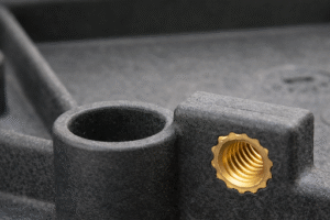
Types of Ejector Pins & Ejection Methods
Different injection molding ejector pins are designed to manage force in different ways. Selecting the correct ejector pin type is essential to prevent stress concentration, surface marking, and premature mold wear—especially in complex or cosmetic parts.
-
Standard / Round Ejector Pins
Standard round ejector pins are the most commonly used type in injection molding. They are cost-effective, easy to replace, and suitable for non-cosmetic surfaces. Poor placement, however, can result in visible pin marks or localized deformation.
-
Through-Hardened Ejector Pins
Through-hardened pins are hardened throughout their entire cross-section. They offer excellent wear resistance and are ideal for high-volume production molds. The trade-off is reduced shock resistance, which can lead to brittle failure under uneven loading.
-
Case-Hardened Ejector Pins (Nitride H13)
Case-hardened pins have a hardened surface with a tougher internal core. This combination provides improved resistance to impact and cyclic loading. These pins are commonly used in demanding industrial and automotive tooling applications.
-
Shoulder Ejector Pins
Shoulder ejector pins include a built-in stop that limits travel distance. They help prevent over-ejection and are useful in thin-wall or precision parts. Controlled stroke improves dimensional stability and reduces the risk of part distortion.
-
Blade (Flat) Ejector Pins
Blade ejector pins are designed with a flat profile to distribute force across narrow features. They are commonly used for ribs, slots, and thin sections where round pins would concentrate stress. Blade pins help reduce cracking and surface damage.
-
Sleeve Ejector Pins
Sleeve ejectors apply force around cylindrical cores such as bosses or posts. This uniform force distribution minimizes stress concentration and reduces visible ejector pin marks. Sleeve pins are ideal for parts with circular geometry or cosmetic requirements.
-
Custom Ejector Pins
Custom ejector pins are shaped to match complex part geometry. They are used when standard pin types cannot safely apply ejection force. While more expensive to manufacture, custom pins often prevent repeated mold rework and part failures.
Common Mold Ejection Problems & Remedies
Most defects associated with ejector pin marks in injection molding are not random failures. They are predictable outcomes of how force, geometry, material behavior, and timing interact during ejection. Addressing the root cause at the design stage prevents repeat tooling corrections, trial delays, and unplanned production downtime.
1. Ejector Pin Marks in Injection Molding
Problem Explanation
Ejector pin marks occur when ejection force is applied to a small surface area that cannot structurally support it. Instead of releasing smoothly, the plastic deforms locally, leaving visible circular or rectangular impressions on the part surface.
Why It Happens
- Pins placed on thin walls or cosmetic surfaces
- Insufficient number of ejector pins
- High ejection force caused by poor draft or heavy texture
- Early ejection before the part has sufficient stiffness
Remedies
- Increase the number of ejector pins to distribute force
- Relocate pins to thicker sections, ribs, or bosses
- Replace point-contact pins with sleeve ejectors or stripper plates
- Increase draft angle or delay ejection slightly to reduce force
2. Part Sticking and Vacuum Lock
Problem Explanation
Parts stick to the core when shrinkage creates an interference fit and trapped air forms a vacuum seal. This causes the part to resist release even when ejector pins apply force, increasing stress on both the part and the ejection system.
Why It Happens
- Deep cores with smooth surfaces
- Insufficient draft angle
- No venting paths for trapped air
- High-shrink materials tightly gripping the core
Remedies
- Add draft to reduce surface contact during release
- Introduce venting or micro-vents to break vacuum
- Use gas or air assist to separate the part from the core
- Apply surface textures strategically to disrupt vacuum formation
3. Bent or Broken Ejector Pins
Problem Explanation
Ejector pins bend or break when they are exposed to uneven or lateral forces instead of axial compression. This typically occurs when pins advance at different rates or when the ejector plate flexes under load.
Why It Happens
- Uneven pin spacing or asymmetric pin layout
- Insufficient ejector plate stiffness
- Missing or poorly placed support pillars
- Ejecting against angled or under-drafted surfaces
Remedies
- Balance pin placement to ensure symmetric force distribution
- Add support pillars beneath the ejector plate
Increase pin diameter or switch to stronger pin materials - Improve draft and ensure ejection is aligned with pull direction
4. Cracking and Stress Whitening
Problem Explanation
Cracking and stress whitening occur when the material is forced to deform beyond its elastic limit during ejection. Instead of releasing cleanly, the plastic fractures or develops white stress lines, especially in brittle materials.
Why It Happens
- Excessive ejection force
- Thin walls or sharp internal corners
- Brittle or glass-filled materials
- Ejection before the part has cooled sufficiently
Remedies
- Use blade ejector pins to spread force over a larger area
- Increase wall thickness or add fillets to reduce stress concentration
- Delay ejection to allow additional cooling and stiffness
- Increase draft to lower required ejection force

Advanced Ejection Technologies In Injection Molding
Advanced ejector pin injection molding technologies focus on controlling force, timing, and part release behavior. These methods reduce mechanical stress on pins while improving consistency, part quality, and tool life.
-
Hydraulic Ejection
Hydraulic ejection systems use independent cylinders to apply controlled force during part release. They are ideal for large, thick-walled, or high-friction parts where mechanical ejector pins alone are insufficient. Precise control over speed and pressure helps prevent part damage.
-
Multi-Stage Ejection
Multi-stage ejection separates the release process into two steps. The first stroke breaks adhesion between the part and core, while the second completes ejection. This approach reduces peak stress on ejector pins and improves part stability during release.
-
Gas or Air Assist Ejection
Gas or air assist ejection introduces compressed air to break vacuum lock. This reduces mechanical load on ejector pins and improves consistency. It is especially effective for deep cores and smooth surface finishes.
-
Integrated Cooling Near Ejection Zones
Cooling channels placed close to cores and ejection areas stabilize the part before release. Uniform cooling lowers shrink-fit forces and reduces sticking. This approach improves both part quality and ejection reliability.
-
Stripper Plates and Sleeve-Based Ejection
Stripper plates and sleeve ejectors distribute force over a larger surface area instead of point contact. This reduces localized stress and visible marks. They are commonly used for thin-walled, cylindrical, or cosmetic parts.
-
Robotic Part Handling
Robotic part handling removes parts immediately after ejection. This prevents parts from falling back into the mold and allows faster mold closing. Automation improves consistency and reduces cycle-to-cycle variation.
Cycle Time Optimization Strategies in Ejection Molding
Advanced ejector pin injection molding technologies focus on controlling force, timing, and part release behavior. These methods reduce mechanical stress on pins while improving consistency, part quality, and tool life.
-
Optimized Ejection Setup
Proper pin count, size, and stroke length reduce unnecessary movement. Balanced force distribution minimizes ejection delays. Optimized setups shorten cycle time without increasing defect risk.
-
Conformal Cooling
Conformal cooling follows part geometry closely, improving heat removal efficiency. Faster and more uniform cooling enables earlier ejection. This directly reduces overall cycle time.
-
Material Selection
Material choice affects how easily a part releases from the mold. Low-friction and lower-shrink materials reduce adhesion and ejection force. Selecting release-friendly grades supports faster cycles.
-
Process Monitoring & Control
Monitoring ejector force and stroke helps detect sticking early. Real-time data allows corrective action before defects occur. This improves uptime and maintains stable cycle times.
-
Partial Solidification Ejection
Partial solidification ejection releases the part before full cooling. This reduces cooling time significantly. The method requires precise control to avoid part deformation.
-
Parallel Movements
Parallel movements overlap mold opening, ejection, and part removal. Eliminating idle time increases throughput. This strategy is critical for high-volume automated production.
Engineer Ejection for Speed and Stability
Advanced ejection choices directly impact cost, quality, and mold life.
Manufyn evaluates ejection and cycle-time trade-offs before tooling is finalized.
Best Practices for Ejector Pin Design
Cycle time in injection molding ejector pins systems is heavily influenced by how quickly and safely a part can be ejected. Optimized ejection strategies allow earlier release without increasing the risk of deformation or cosmetic defects.
-
Design Ejection Early
Ejection should be considered during part design, not after tooling begins. Early planning allows ejector pins to align with ribs, bosses, and non-cosmetic surfaces. Late-stage fixes usually result in visible marks or expensive mold rework.
-
Balance Ejection Forces
Distribute ejection force across multiple pins instead of relying on a few high-load contact points. Balanced force reduces stress, minimizes deformation, and prevents ejector pin marks in injection molding.
-
Avoid Cosmetic and Functional Surfaces
Pins should be kept away from visible faces, sealing areas, and snap-fit features. When cosmetic surfaces cannot be avoided, sleeve ejectors or stripper plates are safer alternatives.
-
Match Ejection to Material Behavior
High-shrink or brittle materials require additional ejection support. Flexible materials release more easily but can deform if over-ejected. Material behavior should always guide pin count and placement.
-
Control Stroke Length
Ejector pins should move only as far as needed to release the part. Excessive stroke increases the risk of distortion and cycle time penalties. Shoulder pins or staged ejection help control movement.
-
Design for Maintenance
Ejector pins are wear components and must be easy to access and replace. Standard pin sizes and clear maintenance access reduce downtime and extend mold life.
Conclusion — Reliable Ejection Starts with Design
Ejector pins are not just tooling components; they are critical mechanical interfaces between the part and the mold. Poor ejection design leads to pin marks, cracking, bent pins, and unstable cycle times. When ejection is engineered early—aligned with material behavior, draft, surface finish, and cooling—the result is consistent release, longer mold life, and predictable production.
Designing for reliable ejection is always cheaper than correcting ejection failures after tooling. By treating ejection as a core design requirement, manufacturers avoid costly rework and ensure smoother ramp-up to full production.
Frequently Asked Questions (FAQs)
What are ejector pins in injection molding used for?
Ejector pins in injection molding are used to push the cooled plastic part off the mold core after the mold opens. They overcome shrinkage, friction, and vacuum forces to release the part without damage.
What causes ejector pin marks in injection molding?
Ejector pin marks in injection molding occur when excessive force is applied to a small contact area. Common causes include poor pin placement, insufficient pin count, lack of draft, or ejecting against thin or cosmetic surfaces.
How many injection molding ejector pins does a part need?
The number of injection molding ejector pins depends on part size, wall thickness, material, and geometry. Larger or thin-walled parts typically require more pins to distribute force evenly and prevent deformation.
Can an ejector pin in injection molding replace proper draft angles?
No. An ejector pin in injection molding cannot compensate for insufficient draft. Poor draft increases friction and ejection force, leading to surface damage, sticking, and pin failure.
When should sleeve ejectors be used instead of standard ejector pins?
Sleeve ejectors should be used when ejecting cylindrical features such as bosses or posts. They apply uniform force around the feature and significantly reduce ejector pin marks compared to point-contact pins.
How does ejector pin injection molding affect cycle time?
Ejector pin injection molding directly affects cycle time because difficult ejection requires longer cooling or slower ejection speeds. Optimized ejection allows earlier release and faster mold reset.
Why should ejector pins be reviewed before tooling?
Reviewing ejector pins before tooling prevents cosmetic defects, bent pins, and mold rework. Early validation of ejector pin placement and force distribution is far more cost-effective than post-tool corrections.
Facing ejector pin marks, sticking parts, or unstable cycle times?
Manufyn evaluates ejection design, pin strategy, and cycle-time impact before tooling—so production runs smoothly from day one.