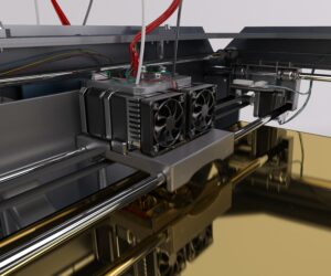
Wrong gate placement creates defects—Manufyn validates flow early.
Gate Size & Placement in Injection Molding Guide
Gate placement in injection molding plays a direct role in how molten plastic enters the mold cavity, controls flow behavior, and influences final part quality. The gate acts as the entry point for polymer flow, making its size, shape, and location critical for achieving proper fill, maintaining dimensional accuracy, and reducing cosmetic defects.
Choosing the wrong gate location often leads to problems like jetting, warpage, short shots, burn marks, and unnecessary tooling modifications. This is why gate size injection molding decisions must be planned early during design, not after tooling is built.
This guide explains how to determine gate size, basic injection mold gate size calculation principles, and best practices for selecting placement based on part geometry, material flow, and production goals.
What is a Gate and Why It Matters
A gate is a controlled opening that connects the runner system to the molded part. It regulates plastic flow, pressure distribution, and cooling across the part surface. The gate’s design determines how smoothly the cavity fills, how quickly the gate freezes off, and what cosmetic marks appear at the entry point.
If the gate is not correctly sized or placed, flow may hesitate, shear may increase, and air traps may form. These issues directly impact strength, appearance, and cycle time. A properly designed gate reduces injection pressure, ensures smooth flow progression, and helps maintain consistent packing for improved dimensional stability.
A gate affects:
- Flow rate and material velocity
- Weld line positioning
- Shear stress and polymer degradation
- Surface finish and visible marks
- Cooling speed and cycle time
Correct gate design is not guesswork. It requires engineering judgment, simulation data, and understanding of material behavior.
Types of Gates Used in Injection Molding
Choosing the right gate type depends on part geometry, polymer type, cosmetic requirements, and production volume. Below are the most common options
| Gate Type | Best For | Key Advantage |
|---|---|---|
| Edge Gate | Simple 2D parts, consumer goods | Easy machining, low cost |
| Submarine/Tunnel Gate | High-volume automatic de-gating | No manual trimming, faster cycle |
| Pin/Direct Gate | Precision parts, circular components | Uniform flow distribution |
| Fan Gate | Wide parts, thin walls | Better flow spread, reduces jetting |
| Tab Gate | Thick-walled sections | Minimizes shear and burn marks |
| Sprue Gate | Large parts, simple molds | Direct fill with strong packing |
| Hot Runner Gate | Mass production, cosmetic surfaces | No runners, reduced waste |
Selecting the correct gate style reduces cycle time, improves fill consistency, and minimizes secondary finishing work.
How to Determine Gate Size for Injection Molding
Determining gate size in injection molding is a balance of flow behavior, shear rate, pressure loss, and freezing time at the gate. A gate must be large enough to fill the cavity efficiently, but not so large that it leads to flashing or extended cooling.
Key Factors That Define Gate Size
- Melt flow index and viscosity grade of the polymer
- Wall thickness and required packing pressure
- Flow length to thickness ratio
- Cycle time requirements and gate freeze-off behavior
- Finished part cosmetic expectations
Practical Decision Guidance
| Requirement | Gate Size Tendency |
|---|---|
| High cosmetic requirement | Smaller gate, controlled feed edge |
| Fiber filled or high viscosity materials | Larger gate cross-section |
| Thin wall parts | Wider gate to reduce shear burn |
| Thick wall parts | Controlled size to avoid sink and overpacking |
When selecting gate size for injection molding, the starting point is always material behavior and flow length. Final confirmation should be validated through simulation or controlled sampling.
Injection Mold Gate Size Calculation Basics
These are non-proprietary sizing rules used as a starting reference during DFM.
General Sizing Ranges (By Material Family)
| Material | Typical Gate Thickness Range |
|---|---|
| PP, PE | 0.8 mm to 1.5 mm |
| ABS, PS | 0.9 mm to 1.6 mm |
| PC, PMMA | 1.0 mm to 2.0 mm |
| Nylon PA6 / PA66 | 1.0 mm to 1.8 mm |
| Glass filled engineering polymers | 1.2 mm to 2.2 mm |
Cross Section Estimation
A simple principle to begin the sizing process:
Gate thickness should be 70 percent to 90 percent of the adjoining wall thickness.
Flow-length to Thickness Guideline
If flow length exceeds 200 mm to 250 mm, increase gate width or switch to a gate style that improves spread, such as fan or tab.
Why This Matters
If the gate is too small:
- High shear rate
- Jetting, hesitation, short shots
- Burn marks due to air trap compression
If the gate is too large:
- Overpacking and flashing
- Visible vestige mark
- Long gate freeze-off and extended cycle time
This is why injection mold gate size calculation should be validated at the design stage, not after tooling investment.
Choosing Gate Placement for Best Filling
Gate placement affects the entire filling sequence. The goal is to place the gate where the material can flow in a balanced path with minimal flow hesitation.
Placement Rules That Prevent Defects
- Position near the thickest wall to control shrink and sink
- Avoid cosmetic surfaces where the vestige will show
- Place in a location that directs weld lines to non-critical regions
- Avoid gating into thin sections where hesitation is likely
- Ensure venting support exists near flow termination points
Engineering Considerations
- For long flow paths, a central gate or multi-gate balancing strategy may be needed
- For circular parts, a pin gate maintains uniform fill
- For complex geometries, mold flow analysis should validate shear, pressure drop, and gate freeze timing
Gate location and gate size must work together. If either is incorrect, the process becomes unstable, leading to repetitive tuning, pressure spikes, or dimensional drift during mass production.
Gate Design Considerations by Material Type
Different polymers behave differently during filling and packing, so gate size and placement must align with material characteristics.
| Material Type | Behavior Notes | Gate Recommendation |
|---|---|---|
| PP, PE (Polyolefins) | Low viscosity, high flow length | Moderate gate size, avoid jetting through small entry |
| ABS, PS (Amorphous) | Sensitive to shear heat, cosmetic priority | Controlled gate cross section to avoid burn and gloss variation |
| PC, PMMA (Engineering Clear) | Shear and heat sensitive, clarity needed | Larger gate to reduce shear, slower fill to prevent splay |
| PA6/PA66 (Nylon) | Absorbs moisture, shrinks after cooling | Slightly larger gate for packing and reduced voids |
| Glass-Filled Materials | High shear stress, abrasive | Larger gate radius to reduce shear and tool wear |
Key Rule:
More shear-sensitive materials require larger gates to reduce velocity spikes and burn marks.

Gate Freeze-Off, Packing Phase, and Dimensional Stability
Gate freeze time determines whether internal pressure remains stable long enough to pack out and compensate for shrinkage.
- If gate freezes too early → insufficient packing → sink marks, vacuum voids, warpage
- If gate freezes too late → overpacking → flashing, dimensional shift, longer cycle time
Ideal Control Window:
Gate freeze should occur after packing has compensated shrinkage but before wasteful pressure retention extends cooling time.
This balance stabilizes shrinkage, surface finish, and dimensional repeatability.
Runner-to-Gate Ratio and Pressure Drop Guidelines
Gate sizing must match the runner cross section. An imbalanced ratio causes pressure loss and inconsistent filling.
General Ratios (Non-Proprietary Guidance):
- Runner diameter should be 2 to 3 times gate thickness for most commodity polymers
- For engineering plastics, runner diameter can be 3 to 4 times gate thickness
Why It Matters:
If the runner is too small → pressure drop increases → short shots and high shear
If the runner is too large → wasted material → longer cycle times
Rule of Thumb:
Adjust gating before increasing injection pressure. Size solves more than pressure does.
When to Use Multi-Gate Designs and How to Balance Flow
Use multiple gates when:
- The flow path is long (large part footprint)
- The part has structural ribs that break flow
- Reinforced materials need even fiber orientation
- A single gate creates weld lines in critical areas
Balancing Strategy
- Symmetrical parts: mirror gate positions
- Long parts: gates spaced along the neutral axis
- Cosmetic parts: avoid gates on the show surface
- High-strength sections: gate closest to load-bearing features
Multi-gate molds must be flow-balanced through sizing and simulation, not guesswork.
Mold Flow Validation Checklist (Before Cutting Steel)
A mold flow study should validate the following parameters:
- Pressure drop across the flow path
- Shear rate at gate entrance
- Weld line location and acceptability
- Fill time vs gate freeze timing
- Packing pressure consistency
- Venting performance at flow endpoints
- Risk of jetting, hesitation, or air trap zones
If two or more of these factors fail simulation, the design must be revised before steel tooling begins.
Troubleshooting Guide: If You See This, Adjust Gate Like This
| Issue | Root Cause | Gate Correction |
|---|---|---|
| Short shots | Restricted flow | Increase gate thickness or width |
| Jetting marks | High velocity spike | Switch to fan gate or radius entry |
| Sink marks | Poor packing feed | Move gate closer to thick areas |
| Burn marks | Air trap and shear heat | Add venting or change gate angle |
| Weld lines | Uncontrolled flow front | Reposition gate to redirect merging |
| Flashing | Overpacking | Reduce gate size or balance pressure |
This table helps diagnose and correct issues during sampling without unnecessary parameter trial and error.
Common Defects Caused by Incorrect Gate Size or Placement
Gate design errors often show up immediately during sampling. These issues come from either incorrect injection mold gate size, wrong location, or mismatched gate style to material flow behavior.
If the Gate Is Too Small
| Problem | Why It Happens |
|---|---|
| Short shots | Flow restriction increases back pressure |
| Jetting or snake-like flow marks | High velocity concentrated through a small entry |
| Burn marks and black spots | Air trap compression and shear heat |
| High shear degradation | Material overheats entering the cavity |
If the Gate Is Too Large
| Problem | Why It Happens |
|---|---|
| Short shots | Flow restriction increases back pressure |
| Jetting or snake-like flow marks | High velocity concentrated through a small entry |
| Burn marks and black spots | Air trap compression and shear heat |
| High shear degradation | Material overheats entering the cavity |
If the Gate Is in the Wrong Location
| Problem | Why It Happens |
|---|---|
| Short shots | Flow restriction increases back pressure |
| Jetting or snake-like flow marks | High velocity concentrated through a small entry |
| Burn marks and black spots | Air trap compression and shear heat |
| High shear degradation | Material overheats entering the cavity |
These outcomes reinforce why a proper injection mold fill gate size and placement evaluation is essential before tool steel is cut.
How Manufyn Supports Gate Design and Mold Optimization
Manufyn provides engineering-led support to help manufacturers prevent design and tooling issues that lead to scrap, mold rework, or extended sampling time. The goal is to achieve stable cavity filling and repeatable performance during mass production.
Manufyn services include:
- Gate size assessment based on material and part geometry
- Gate placement decisions using simulation and flow path mapping
- Mold flow support for shear rate, packing phase, and cooling behavior
- Part and runner system DFMA before mold build
- Tooling vendor coordination for correct steel execution
- Sample run assistance and parameter stabilization
- Feedback loop for scaling production volumes
This approach reduces the risk of retooling and accelerates first-off production approval. Instead of trial and error, Manufyn focuses on data-backed decisions to ensure parts reach dimensional stability faster with fewer adjustments.
If you need support for gate size injection molding evaluations, mold development, or sampling stability, Manufyn provides full-cycle assistance.
Conclusion
Gate size and placement are central to stable mold performance, consistent cavity filling, and long-term part quality. Incorrect decisions at this stage lead to avoidable production defects, sampling delays, and cost overruns. By understanding flow behavior, sizing principles, and placement rules, manufacturers can improve quality and reduce the need for mold rework.
For reliable results, engineering validation is necessary before tool steel is cut. This is where Manufyn provides value through design evaluation, simulation guidance, and tooling support.
Frequently Asked Questions
How do you determine gate size in injection molding?
By evaluating material viscosity, wall thickness, flow length, and required packing pressure. Gate sizing starts from reference thickness ratios and is validated through simulation and controlled sampling.
What affects injection mold gate size calculation the most?
Material grade, shear sensitivity, part thickness, flow resistance, and gate freeze behavior are the primary factors influencing calculation.
What is a typical gate size for PP or PE?
PP and PE usually fall in the range of 0.8 mm to 1.5 mm depending on flow distance and part thickness.
How do I avoid jetting during filling?
Increase gate width or switch to a gate style that spreads flow, such as a fan gate, to reduce entry velocity.
Can gate size solve sink marks?
Increasing gate size near thick sections improves packing pressure, which can reduce sink marks.
Why do weld lines appear even when gate size is correct?
Incorrect gate placement, not size, usually causes weld lines. Flow fronts are meeting in a visible or structurally weak zone.
Does each material need a different gate size?
Yes. High viscosity and fiber reinforced materials generally need larger gates to prevent shear overheating.
What is the best gate type for precision parts?
Pin gates or submarine gates are preferred for automatic trimming and clean vestige control.
When should a hot runner gate be used?
For high volume production, cosmetic surfaces, and runner waste elimination in engineering-grade materials.
Does Manufyn help with tool change or gate redesign?
Yes. Manufyn supports gate resizing, placement correction, simulation advice, and vendor coordination for modifications.
Need help with gate placement, sizing decisions, or mold sampling?
Manufyn provides DFMA guidance, tooling support, and production optimization for global clients.