
Prototype Dimensional Inspection: Methods, Tolerances and Quality Control
How to Verify Prototype Dimensions Before Design Validation
A prototype can look correct and still fail to assemble, function or meet its engineering requirements. Learn how dimensional inspection verifies critical features, evaluates tolerances and identifies manufacturing deviations before moving to the next development stage.
What Is Prototype Dimensional Inspection?
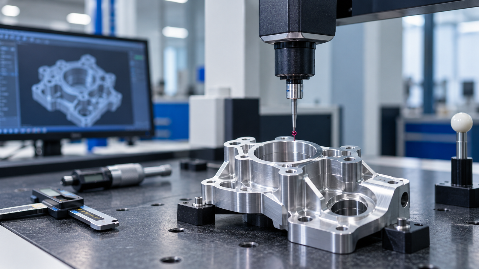
Prototype dimensional inspection is the systematic measurement of a prototype component against its approved engineering drawing, CAD model and specified acceptance criteria.
During product development, prototypes help engineers evaluate geometry, assembly fit, functionality and manufacturability. However, visual confirmation alone cannot establish whether a component meets its dimensional requirements. Features such as hole positions, bore diameters, wall thicknesses, flatness and mounting interfaces require appropriate measurement methods.
Dimensional inspection converts those requirements into measurable results. Engineers can compare actual dimensions with specified limits, identify deviations and determine whether a design or manufacturing adjustment is necessary.
The inspection process is particularly important for CNC machined components, injection molded prototypes, sheet metal parts and additively manufactured components intended for functional testing.
Verify dimensions
Confirm that measured features meet the dimensional requirements specified on the approved engineering drawing.
Validate functionality
Check critical interfaces and geometric relationships that influence assembly, movement and functional performance.
Prevent repeat issues
Identify deviations early and establish corrective actions before pilot production or larger manufacturing quantities.
Why Is Dimensional Inspection Important for Prototypes?
Prototype manufacturing is an iterative process. Engineers may change hole locations, wall thicknesses, mating surfaces or material selections several times before approving a final design. Dimensional inspection provides objective evidence about the manufactured result at each stage.
Design verification
Inspection helps determine whether the manufactured geometry matches the intended design. This is especially important when a prototype is used to validate a new mechanism, housing or precision interface.
Assembly fit
Two components may individually meet their size requirements yet fail to assemble because of positional variation, datum relationships or accumulated tolerances. Inspection should consider these functional relationships.
Manufacturing feedback
Inspection results can reveal tool deflection, fixture errors, material movement, shrinkage or other process-related variations. This information helps engineers and manufacturers improve the next iteration.
Production readiness
Before transitioning to low-volume production, teams can use inspection results to identify unresolved dimensional issues and determine which characteristics need additional process controls.
Step by Step Prototype Dimensional Inspection Process
An effective inspection starts with the engineering requirements. Selecting a measuring instrument before understanding the drawing can result in incomplete measurements or incorrect acceptance decisions.
Step 1. Review the engineering drawing
Confirm the part number, drawing revision, units, nominal dimensions, tolerances, datum references, GD&T callouts and critical characteristics. Resolve unclear requirements before measurement.
Step 2. Define the inspection plan
Identify which features must be inspected, the sample quantity, the measuring equipment and the required reporting format. Prioritize characteristics that directly affect fit or function.
Step 3. Prepare the component
Remove loose chips and contamination. Check whether temperature stabilization, material conditioning or special support is necessary for the part and its specified tolerance.
Step 4. Establish the datum reference
Position the component according to the applicable datum scheme. Use suitable fixtures or measurement alignment without introducing distortion, particularly on thin walls and flexible components.
Step 5. Measure and compare
Record the actual measurements and evaluate them against the drawing limits. Use appropriate methods for size, position, form, orientation and profile requirements.
Step 6. Document the outcome
Record conformance, identify deviations and communicate the required disposition. Rework, remanufacture or engineering approval should follow the agreed quality process.
Related reading: CNC machining processes and rapid prototyping methods.
Equipment Used for Prototype Dimensional Inspection
Different instruments suit different features. The choice depends on geometry, access, tolerance, material, measurement uncertainty and the required level of documentation.
| Equipment | Typical application | Key consideration |
|---|---|---|
| Digital caliper | General lengths, widths and accessible diameters. | Not automatically suitable for tight-tolerance or difficult-to-access features. |
| Micrometer | Outside diameters, thicknesses and selected bore measurements. | Correct contact geometry and measuring force are important. |
| Height gauge | Heights, step dimensions and selected coordinate measurements. | Requires suitable datum establishment and a stable reference surface. |
| Coordinate Measuring Machine (CMM) | Three-dimensional coordinates, hole positions and geometric relationships. | Probe strategy, alignment, temperature and programming affect results. |
| Vision Measuring Machine (VMM) | Small features, profiles, edges and selected two-dimensional measurements. | Lighting, edge definition and surface reflectivity must be controlled. |
| Optical or 3D scanner | Complex contours and comparison of measured surfaces with CAD data. | Scanner uncertainty, surface properties and alignment influence the comparison. |
| Dial indicator | Comparative measurements, runout and selected alignment checks. | Requires a suitable fixture, reference and measurement procedure. |
When should you use a CMM?
A CMM is particularly useful when prototype parts contain complex geometries, multiple datum relationships, precision hole patterns or geometric tolerances that are difficult to evaluate with manual instruments. It can generate coordinate data and structured inspection reports when configured for the required characteristics.
However, a CMM is not automatically necessary for every prototype. Straightforward dimensions may be measured more efficiently using calibrated manual instruments when their capability is appropriate for the specified tolerance.
How to Interpret Prototype Manufacturing Tolerances
A dimensional tolerance defines the permissible variation from a nominal dimension. Inspection determines whether the measured result falls within the applicable specification limits.
Example: A dimension with a bilateral tolerance
Consider a nominal dimension of 20.00 mm with a specified tolerance of ±0.10 mm. The lower specification limit is 19.90 mm and the upper specification limit is 20.10 mm. A measurement is evaluated against those limits, subject to the applicable drawing conventions and acceptance rules.
| Characteristic | What is evaluated? | Inspection approach |
|---|---|---|
| Linear size | Length, width, height or distance. | Appropriate calibrated dimensional instrument. |
| Diameter | Size of a bore, shaft or cylindrical feature. | Micrometer, bore gauge, CMM or another suitable method. |
| Position | Location of a feature relative to the specified datum reference frame. | CMM, suitable coordinate method or a dedicated functional gauge. |
| Flatness | Form variation of a surface. | Suitable surface measurement method under controlled conditions. |
| Profile | Variation of a line or surface from its specified profile. | CMM, optical measurement or scanning where appropriate. |
| Runout | Variation relative to the specified datum axis or reference. | Dial indicator setup or an appropriate coordinate measurement method. |
How Materials and Manufacturing Processes Affect Dimensions
CNC Machined Metal Parts
Aluminum, stainless steel and other metals can experience thermal expansion, residual-stress-related distortion and changes caused by machining or clamping. Thin walls and long unsupported features require particular attention.
Related resource: CNC machining.
Engineering Plastic Components
Nylon, PEEK, ABS and other polymers may exhibit moisture-related dimensional changes, thermal expansion, creep and elastic deformation. Material conditioning and contact force may influence the results.
Related resource: Prototype injection molding.
3D Printed Prototypes
Build orientation, shrinkage, support removal and post-processing can influence dimensional accuracy. Inspect the component in the condition specified for its intended use.
Related resource: Rapid prototyping.
Injection Molded Prototypes
Shrinkage, warpage, cooling conditions and material selection can affect molded dimensions. Inspection timing and conditioning requirements should be defined in the inspection plan.
Related resource: Manufacturing Resource Hub.
What Should a Prototype Inspection Report Include?
A useful dimensional inspection report makes it possible to trace each measured result to a specific part, drawing revision and characteristic. It also allows engineers to distinguish actual dimensional deviations from misunderstandings about the acceptance criteria.
Part identification
- Part name and part number.
- Drawing revision and applicable specification.
- Supplier and inspection date.
- Sample or serial number, where applicable.
Measurement results
- Characteristic identification.
- Nominal dimensions and tolerance limits.
- Actual measured values and units.
- Conformance status and recorded deviations.
Inspection traceability
- Equipment identification where required.
- Inspection method and relevant setup details.
- Inspector and review information.
- Supporting CMM or measurement records when required.
Additional quality records
- Material and finishing certificates where applicable.
- Nonconformance reports and corrective actions.
- Customer-specific FAI or PPAP documentation.
- Approved engineering deviations where applicable.
Prototype inspection versus first article inspection
A prototype dimensional report records measurements for a prototype part. First Article Inspection (FAI) is a defined verification activity used to document conformance of an initial production article to applicable requirements. Its scope depends on the customer, industry and governing specification.
The two activities may overlap, but they should not automatically be treated as interchangeable.
Common Dimensional Inspection Mistakes
Using the wrong datum reference
Measuring from an arbitrary edge rather than the drawing’s intended datum can produce misleading results for hole position and alignment.
Selecting unsuitable equipment
The instrument must provide appropriate measurement capability for the tolerance and feature geometry. Instrument resolution alone does not establish measurement accuracy.
Ignoring temperature and conditioning
Temperature differences, moisture and part deformation can affect measurements, especially for precision features and engineering plastics.
Reporting only pass or fail
Actual measurement results and specification limits provide much more useful engineering information than an unexplained acceptance status.
Inspecting at the wrong process stage
Coatings, anodizing, plating and other finishing operations may affect dimensions. Confirm whether the drawing requires inspection before or after finishing.
Using an obsolete drawing
Confirm the approved drawing revision before measurement. Accurate measurements against outdated requirements can still lead to incorrect acceptance decisions.
Prototype Dimensional Inspection FAQs
What is the purpose of prototype dimensional inspection?
It verifies that prototype dimensions and specified geometric characteristics conform to the engineering requirements. The results help identify deviations before functional testing, design approval or production.
Which instruments are used for prototype inspection?
Common instruments include calipers, micrometers, height gauges, coordinate measuring machines, vision measuring machines and optical scanners. Selection depends on the feature geometry, tolerance and required measurement capability.
What is the difference between CMM and VMM inspection?
A CMM measures three-dimensional coordinates and is useful for complex feature relationships. A VMM uses optical measurement and is often suitable for small features, edges and two-dimensional profiles. The appropriate method depends on the inspection requirement.
Can prototype parts meet tight dimensional tolerances?
Yes, provided the selected manufacturing process, material, geometry and inspection method can support the specified requirements. Feasibility should be confirmed during design for manufacturability and RFQ review.
Does dimensional inspection guarantee functional performance?
No. Dimensional inspection verifies specified measurable characteristics. Functional performance may also depend on material properties, assembly conditions, surface finish, strength and application-specific testing.
What is the difference between prototype inspection and FAI?
Prototype inspection covers the agreed dimensional checks on a prototype. First Article Inspection documents conformance of an initial production article to applicable requirements and may include broader customer-specific documentation.
What should be included in a dimensional inspection report?
Typical information includes part identification, drawing revision, nominal dimensions, tolerance limits, actual values, conformance status and relevant equipment or traceability details.
Build Dimensional Verification Into the Prototype Process
Prototype dimensional inspection is most effective when measurement requirements are defined before manufacturing begins.
Clear drawings, appropriate datum references, suitable measurement equipment and traceable inspection reports help engineering teams identify dimensional issues early. They also create a stronger basis for design iterations, supplier communication and production planning.
For manufacturers and procurement teams, the objective is not simply to obtain a measurement report. It is to ensure that the inspection method, acceptance criteria and manufacturing process are aligned with the part’s intended function.
Explore Manufacturing and Quality Engineering
Continue exploring Manufyn’s technical resources, case studies and manufacturing articles to understand the relationship between prototype development, process capability and product quality.
Author: Naman Agarwal , Project Manager at Manufyn India Private Limited.
This article provides general engineering guidance. Actual inspection methods and acceptance decisions must follow the approved drawing, applicable standards and customer requirements.