
CNC Machining for Robotics: 7075-T6 Aluminium Components with Black Hard Anodising
Precision machined mounting brackets, linear motion attachments and custom aluminium components manufactured to engineering drawing requirements.
Explore how Manufyn supports robotics manufacturers with custom CNC machining, drawing driven manufacturing, precision features and surface treatment coordination through India’s manufacturing network.
Request a CNC Machining Quote Explore Robotics Manufacturing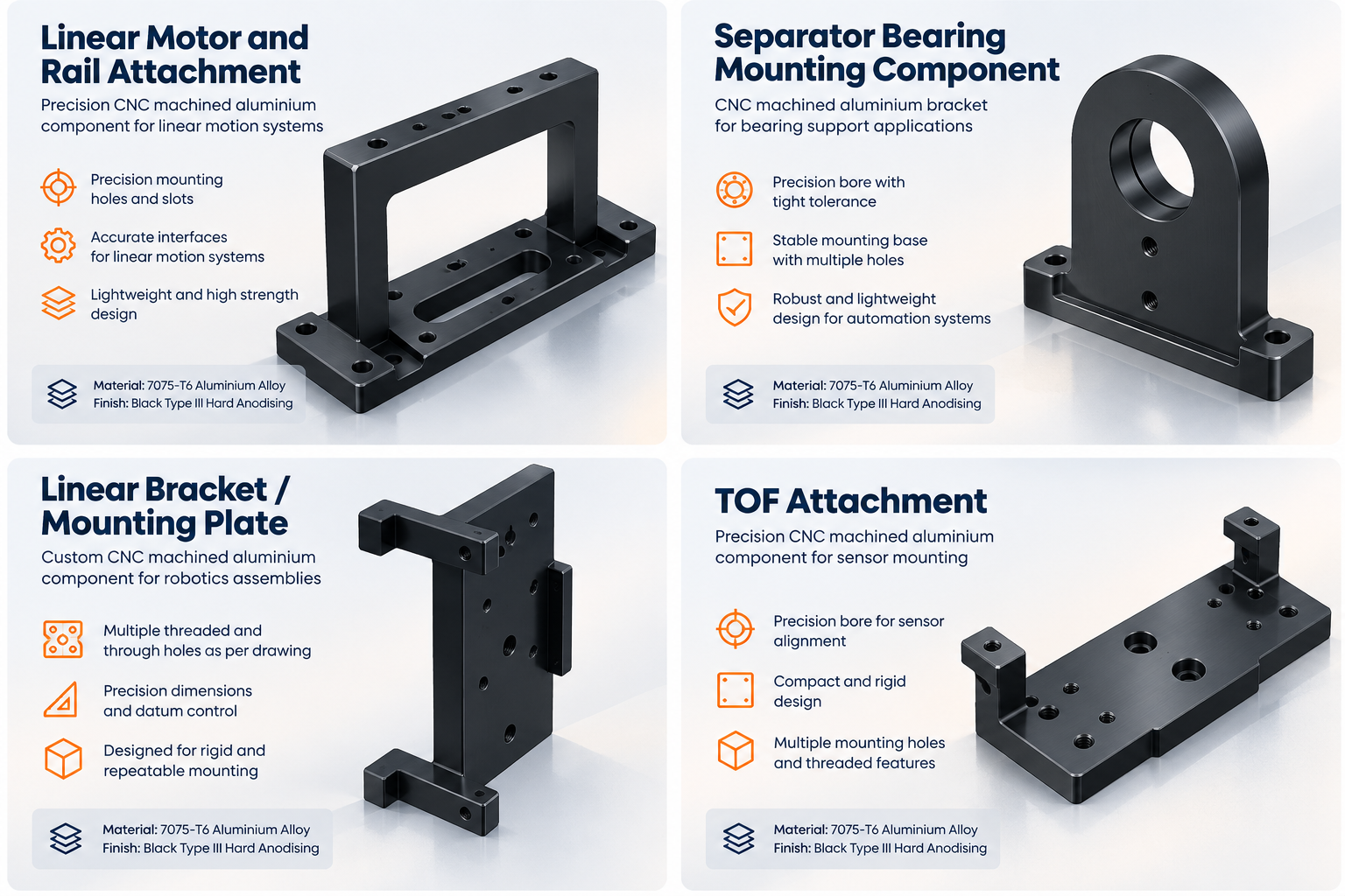
Project Overview
Robotics and industrial automation systems require precision mechanical components that fit correctly within complex assemblies. Mounting brackets, bearing supports, linear motion attachments and custom fixtures often incorporate multiple holes, threaded features, locating bores and closely controlled interfaces.
Manufyn developed a set of custom components for a robotics company using 7075-T6 aluminium alloy with black Type III hard anodising specified on the engineering drawings. The parts included a linear motor and rail attachment, a separator bearing mounting component and a TOF attachment.
The project demonstrates our approach to CNC machining for robotics applications, where material selection, hole positioning, datum control, machining sequence and surface treatment all contribute to a component’s manufacturability.
Application: Robotics and precision mechanical assemblies
Material: 7075-T6 aluminium alloy
Manufacturing process: CNC milling and precision machining
Surface treatment: Black Type III hard anodising, as specified
Part types: Linear motor attachment, bearing mounting component and TOF attachment
Customer Requirements and Manufacturing Challenges
The supplied engineering drawings specified several functional features that needed to be considered together during manufacturing. The challenge was not simply to machine the external profile, but to maintain the relationships between locating features, mounting interfaces and the component datums.
1. Precision hole locations and bores
The parts incorporated precision hole features, including H7 tolerance bores on specified components, as well as clearance holes and counterbores. These features can affect component alignment and assembly fit, making correct machining and verification important.
2. Threaded mounting interfaces
The drawings included small threaded features such as M2, M2.5 and M3 where specified. Thread preparation, tapping depth, hole positioning and burr removal must be considered to ensure the interfaces meet drawing requirements.
3. Geometric dimensioning and tolerancing
Position, parallelism, flatness and datum references define how selected features relate to one another. Reviewing the GD&T requirements before machining helps determine the appropriate workholding, setup sequence and inspection method.
4. Lightweight structural components
7075-T6 aluminium provides high strength relative to its weight, making it a candidate material for many robotics and automation components. However, the alloy’s suitability depends on the application’s loads, fatigue requirements and operating environment.
5. Hard anodising and dimensional control
Black Type III hard anodising was specified on the drawings. Coating growth can affect dimensions and fits, so critical bores, threads and mating surfaces need to be reviewed before treatment. Masking and post-treatment verification should follow the drawing and agreed inspection plan.
For additional technical context, see our guides to GD&T for CNC machining, hole and thread design and CNC datum selection.
Manufacturing Approach
Step 1: Engineering drawing review
The first stage is to review the 2D drawings and available 3D CAD models, identify critical dimensions, establish the relevant datum references and assess the specified surface treatment. This review helps identify features that require particular attention during machining and inspection.
Step 2: CNC milling and profile machining
CNC milling is suitable for producing the mounting plates, raised supports, slots, pockets and profiles shown on these components. The machining strategy should consider tool access, stock removal, workpiece rigidity and the number of setups required.
Explore Manufyn’s CNC machining capabilities and our guide to the CNC machining process.
Step 3: Hole machining and threading
Drilling, boring, reaming and tapping may be selected according to the hole specification and required tolerance. Precision locating bores should be evaluated separately from ordinary clearance holes because their functional requirements and inspection needs may differ.
Step 4: Surface treatment coordination
The black Type III hard anodising requirement must be communicated clearly to the finishing supplier. The specified alloy, coating requirements, masking locations and critical dimensions should be reviewed before processing. Functional dimensions must be verified against the drawing’s acceptance criteria.
Step 5: Dimensional inspection
Inspection should be based on the critical-to-function characteristics identified during drawing review. Depending on the requirements, this may include checking bore diameters, hole positions, threads, mounting surfaces, flatness and parallelism.
Read more about CNC inspection and CMM inspection services in India.
Components Developed for the Robotics Application
Linear Motor and Rail Attachment
This component features a mounting structure with multiple precision holes, threaded interfaces and machined locating features. The key manufacturing consideration is maintaining the required relationship between the mounting faces and the specified hole pattern.
Separator Bearing Mounting Component
This component incorporates a raised support frame, a base plate, mounting holes and a machined opening. Its geometry requires appropriate workholding and careful attention to the mounting interfaces and the relationship between the upright support and the base.
TOF Attachment
The TOF attachment includes a raised section, a central precision bore and mounting interfaces. The drawing specifies bore tolerances and geometric controls that need to be considered during machining and inspection.
Each part has its own drawing requirements. The final acceptance criteria should therefore be defined and verified individually rather than assumed to be identical across the component set.
Manufacturing Specifications at a Glance
| Parameter | Project requirement |
|---|---|
| Material | 7075-T6 aluminium alloy |
| Primary process | CNC milling and precision machining |
| Component geometry | Mounting brackets, supports, slots, profiles and bores |
| Hole features | Precision bores, clearance holes and counterbores, as specified |
| Threads | Drawing specified M2, M2.5 and M3 features on relevant parts |
| Surface treatment | Black Type III hard anodising |
| Quality requirements | Dimensional and geometric verification against approved drawings |
Note: The table summarises drawing requirements. Actual inspection results, production quantities, lead times and commercial outcomes should only be added when verified project records are available.
Why 7075-T6 Aluminium Is Used in Robotics
Robotics engineers often need components that combine strength, low weight, machinability and accurate interfaces. 7075-T6 aluminium is one option for these requirements, although the correct material depends on the application’s mechanical and environmental conditions.
- Strength to weight ratio: Useful where component mass and structural performance must be balanced.
- Machinability: Suitable for many milled profiles, pockets, holes and precision mounting features.
- Complex geometry: CNC machining supports custom brackets, mounting plates, fixtures and interfaces.
- Surface treatment: Anodising can provide a functional oxide layer and a specified black appearance.
Material selection should also consider corrosion exposure, fatigue, contact conditions, coating requirements and the service environment. Hard anodising does not eliminate the need to evaluate these factors.
Explore our related resource on aluminium CNC machining and our guide to aluminium CNC parts for robotics.
How Manufyn Supports Robotics Manufacturers
Manufyn helps engineering and procurement teams evaluate manufacturing requirements and connect with suitable manufacturing capabilities in India. Our role can include supplier identification, drawing review coordination, quotation management, quality follow up and procurement support.
- Custom CNC machined aluminium parts for robotics and automation.
- Precision brackets, bearing supports, mounting plates and mechanical interfaces.
- Prototype and low volume manufacturing feasibility assessment.
- Coordination of specified surface finishing and inspection requirements.
- Supplier development and manufacturing procurement support.
- Support for international buyers managing manufacturing requirements in India.
Learn more about CNC machining for robotics, robotics contract manufacturing and India purchasing office services.
Related Resources for Robotics Engineers and Buyers
Use these technical resources to assess design requirements, manufacturing feasibility and supplier qualification before releasing a new component for production.
Frequently Asked Questions
Can Manufyn support CNC machining for robotics components?
Manufyn supports the development and procurement of custom CNC machined components based on customer supplied drawings and CAD models, subject to manufacturing feasibility and supplier capability.
Is 7075-T6 aluminium suitable for CNC machined robotics parts?
7075-T6 offers high strength relative to its weight and can suit many robotics brackets, supports and mechanical interfaces. Suitability depends on loading, fatigue, corrosion exposure and the operating environment.
Can CNC machined aluminium parts receive black hard anodising?
Yes. Black Type III hard anodising can be specified for suitable aluminium components. The alloy, coating requirements, dimensional allowances and masking requirements should be reviewed before manufacturing.
What files are required for a CNC machining quotation?
Provide a 3D STEP file, dimensioned 2D engineering drawing, material specification, surface finish requirements, quantity, inspection requirements and delivery destination wherever available.
Can Manufyn support prototype and low volume robotics components?
Manufyn can assess prototype and low volume CNC machining requirements, subject to part complexity, quantity, manufacturing feasibility, inspection requirements and supplier capability.
How do I request a quotation for custom robotics components?
Contact Manufyn with your drawings, CAD files, quantity and target delivery date to begin a manufacturing feasibility review.
Need Precision CNC Machined Parts for Your Robotics Project?
Send Manufyn your engineering drawings or 3D CAD files for a manufacturing feasibility review. Tell us your material, quantity, surface finish, inspection requirements and target delivery date.
We support international buyers looking for custom CNC machining and engineered components through India’s manufacturing network.
Request a Manufacturing Quote View CNC Machining Services