
CNC Prototype Deburring: Edge Finishing for Precision Machined Parts
Learn how burr removal improves the safety, fit, function and finish of CNC machined prototypes. Explore deburring methods, edge break requirements and inspection considerations for functional prototype parts.
Manufyn coordinates prototype manufacturing and finishing through qualified Indian manufacturing suppliers for engineering teams in the USA and other international markets.
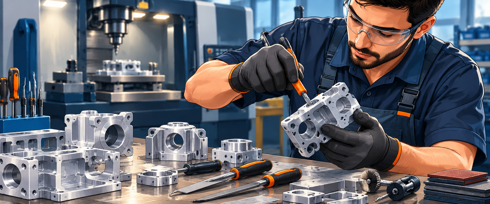
What Is CNC Prototype Deburring?
CNC prototype deburring is the process of removing unwanted material projections, sharp edges and burrs left after milling, turning, drilling, tapping or other machining operations. Burrs commonly form where a cutting tool enters or exits a surface, at intersecting holes, around slots and along machined edges.
Even when a prototype meets its main dimensional requirements, a remaining burr can prevent proper assembly, interfere with a mating surface, affect a seal or create a handling hazard. Deburring is therefore an important finishing and quality-control step.
The objective is not simply to remove material. It is to achieve the specified edge condition without damaging adjacent surfaces or changing critical dimensions.
Deburring vs. Edge Breaking vs. Chamfering
Deburring: Removes unwanted material projections produced during manufacturing.
Edge breaking: Removes the sharpness of an edge to create a controlled, small radius or bevel.
Chamfering: Produces a defined angled surface, often to assist assembly, thread entry or fastener seating.
These operations can overlap, but they are not interchangeable in every drawing or application. Follow the specified edge geometry.
Why Deburring Matters for Prototype Parts
Prototype parts are frequently used to evaluate fit, movement, sealing, assembly and functional performance. Uncontrolled burrs can distort those evaluations and create problems that are mistakenly attributed to the design.
Safe Handling
Removes sharp projections that can cut operators during handling, inspection and assembly.
Assembly Fit
Helps mating components seat correctly and prevents unwanted interference at interfaces.
Functional Testing
Reduces the risk of burrs affecting sliding features, clearances, fluid passages or sealing surfaces.
Consistent Finish
Prepares prototype parts for inspection, customer evaluation and compatible secondary finishing processes.
Where Do Burrs Form on CNC Machined Parts?
Burr formation depends on the material, cutting parameters, tool geometry, tool condition and the way a machining operation exits the workpiece. Review these areas during design and inspection.
External Edges
Edges around milled profiles, shoulders and cutouts can retain thin material projections after the tool exits the workpiece.
Cross-Drilled Holes
Intersecting holes and internal passages can produce burrs that are difficult to access with conventional hand tools.
Threads and Countersinks
Thread starts, tapped holes and countersink edges may need controlled finishing to support fastener engagement and seating.
Slots and Thin Walls
Thin features may deform during aggressive deburring, so tool pressure and material removal must be controlled.
Pockets and Internal Features
Deep pockets, narrow channels and intersecting features can restrict tool access and make burr removal more challenging.
Drilled Breakthroughs
Tool breakthrough on the opposite face of a hole can leave a raised edge that requires attention on both sides.
Deburring Methods for CNC Prototypes
The appropriate process depends on the material, burr size, part geometry, accessibility, quantity and required edge condition. Manual finishing often suits one-off prototypes, while specialized processes can be useful for repeated or difficult-to-access features.
1. Manual Deburring
Uses hand scrapers, deburring blades, files and suitable abrasive tools.
- Useful for one-off and low-volume prototypes.
- Allows localized control around complex geometry.
- Operator technique affects repeatability.
2. Mechanical Deburring
Uses rotary brushes, abrasive wheels or dedicated deburring tools.
- Suitable for accessible edges and repeatable features.
- Can improve consistency across batches.
- Tool pressure must be controlled near precision surfaces.
3. Vibratory Finishing
Uses media and controlled motion to finish multiple parts together.
- Useful for compatible small parts and larger batches.
- Media selection affects the finish.
- May not suit delicate features or tight dimensional limits.
4. Abrasive Flow Finishing
Moves abrasive media through or across selected surfaces and passages.
- Can address certain internal passages.
- Requires suitable geometry and process development.
- Not necessary for every prototype.
5. Thermal Deburring
Uses a controlled thermal process to remove selected burrs, including in difficult-to-reach areas.
- Application depends on material and part design.
- Requires specialized equipment and process controls.
- Compatibility must be reviewed before use.
6. Electrochemical Deburring
Uses controlled electrochemical material removal on suitable conductive materials.
- Can target selected difficult features.
- Requires suitable electrodes and process setup.
- Material compatibility and dimensional effects must be assessed.
Choosing a Deburring Method by Prototype Requirement
| Requirement | Method to Evaluate | Important Consideration |
|---|---|---|
| One-off prototype with accessible edges | Manual deburring | Specify edge condition and inspect critical features. |
| Repeated external edges | Mechanical brushing or dedicated tooling | Control consistency and avoid rounding adjacent surfaces. |
| Multiple small parts | Vibratory finishing, where suitable | Assess media access, part-to-part contact and surface finish. |
| Internal passages or intersections | Specialized abrasive or electrochemical processes | Verify accessibility, material compatibility and inspection method. |
| Precision mating or sealing interfaces | Controlled localized finishing | Protect critical dimensions and functional surfaces. |
This is a selection guide, not a universal process specification. Final method selection should be based on the drawing, material, geometry and acceptance criteria.
Materials Used in CNC Prototype Deburring
Material properties influence burr formation, the effort required for removal and the risk of damaging the finished part.
Aluminum Alloys
Aluminum 6061 and 7075 are common CNC prototype materials. Their machinability and relatively soft surfaces make controlled edge finishing important, particularly around thin walls and precision features.
Stainless and Mild Steel
Stainless steels such as 304 and 316, as well as mild steel, may develop tenacious burrs depending on the cutting process. Tool choice and material behavior influence removal effort.
Brass and Copper
These materials can form sharp edges and delicate projections. Finishing should account for material softness, thin features and the desired surface condition.
Engineering Plastics
Nylon, ABS, polycarbonate and POM can require sharp, suitable tools and controlled pressure to avoid smearing, melting or damaging edges.
PEEK and Ultem
High-performance thermoplastics may be used in demanding engineering applications. Deburring should protect functional features and avoid surface damage.
Titanium and Other Alloys
Specialized materials may need process-specific tools and additional attention to heat, surface integrity and dimensional requirements.
For material selection, see our CNC prototype material selection guide and engineering materials library.
Edge Breaks, Tolerances and Surface Finish
Deburring is a finishing operation, but it can also change the geometry of a part. Excessive material removal can enlarge an opening, round a datum edge, affect a narrow land or alter the effective contact area of a mating component.
Avoid relying on an unspecified instruction such as “remove all burrs” when the edge is functionally important. Define an acceptable edge condition using a drawing note, chamfer dimension, radius, edge-break range or other measurable requirement.
What should the drawing specify?
- Edges that require a defined chamfer or radius.
- Edges that must remain sharp or preserve a datum.
- Critical bores, threads, sealing surfaces and mating features.
- Surface finish requirements on functional areas.
- Inspection method and acceptance criteria.
Typical Drawing Requirements
Edge break: Specify the permitted edge condition or a dimensional range.
Chamfer: Define angle and size where the geometry matters.
Radius: State the required radius and tolerance where applicable.
Surface roughness: Specify an Ra value or other applicable finish requirement for the relevant surface.
Critical dimensions: Identify features that must remain within tolerance after finishing.
Quality Control After Deburring
A prototype should not be accepted solely because its edges look smooth. Inspection should confirm that burrs have been removed where required and that the finishing process has not compromised the component’s dimensions or function.
- Visual inspection under suitable lighting.
- Verification of specified edge breaks and chamfers.
- Dimensional checks using appropriate calibrated instruments.
- Inspection of holes, slots, threads and internal intersections.
- Surface finish verification where specified.
- Functional fit or assembly checks when required.
- First article inspection and reports when agreed.
Inspection Tools and Documentation
Calipers, micrometers, pin gauges, thread gauges, optical inspection equipment and coordinate measuring machines (CMMs) may be used according to the feature and required accuracy.
CMM inspection can verify relevant dimensions and geometric characteristics, but it should be supplemented with a suitable method for detecting small burrs and assessing edge quality.
For prototype programs that require traceability, agree on the inspection report format, material documentation, acceptance criteria and any first article requirements before production.
Read more about Manufyn’s CNC machining capabilities and discuss the inspection requirements for your prototype.
What Affects CNC Prototype Deburring Cost?
Deburring cost depends on the work required to achieve the specified edge condition, not simply on the outside dimensions of a part.
Part Geometry
Deep pockets, intersecting holes, narrow slots and inaccessible features can increase finishing time.
Material
Hardness, ductility, chip formation and thermal sensitivity affect burr characteristics and removal methods.
Edge Requirements
Defined chamfers, radii, tight dimensional limits and protected edges require additional control.
Quantity
A one-off part may favor manual finishing, while repeated parts may justify dedicated tooling or batch processes.
Inspection
Detailed inspection plans, reports and critical-feature verification can add processing and documentation time.
Secondary Finishing
Anodizing, plating, passivation or coating may require additional preparation and verification of surface condition.
How to Specify Deburring on a CNC Prototype RFQ
Clear requirements help the manufacturing supplier quote the right process and reduce ambiguity during inspection and delivery.
Information to Include
- 3D CAD file and revision-controlled 2D drawing.
- Material grade and condition.
- Prototype quantity and future volume estimate.
- Critical edges, holes, threads and mating surfaces.
- Required chamfers, radii or edge-break limits.
- Surface finish and secondary process requirements.
- Inspection and documentation requirements.
- Delivery destination and required date.
Questions to Resolve Before Production
- Which edges are functional or safety-critical?
- Are any edges required to remain sharp?
- Can the deburring tool reach every required feature?
- Will finishing affect a datum or tolerance-critical surface?
- Is burr inspection required on internal passages?
- Does the part require coating or plating afterward?
From CNC Prototype to Low-Volume Production
Prototype finishing requirements often evolve as a design moves from initial fit checks to functional testing and production validation. A process suitable for three hand-finished parts may not provide the consistency or cost structure needed for hundreds of components.
1. Prototype
Validate geometry, material, fit and the required edge condition.
2. Design Validation
Identify burr-sensitive interfaces and refine drawing requirements.
3. Process Standardization
Agree on deburring methods, inspection points and acceptance criteria.
4. Low-Volume Production
Review repeatability, batch economics, documentation and delivery planning.
Explore rapid prototyping services, CNC machining and rapid prototyping examples to understand how prototype requirements connect to broader manufacturing needs.
How Manufyn Coordinates CNC Prototype Finishing
For US engineering teams purchasing prototype parts from India, coordinating machining, finishing, inspection and export logistics through multiple suppliers can add communication and schedule risks. Manufyn provides procurement and manufacturing coordination through its Indian supplier network.
Technical Review
Review drawings, materials, edge requirements and inspection needs before supplier quotation.
Supplier Coordination
Coordinate suitable manufacturing and finishing capabilities, RFQ comparisons and production follow-up.
Quality and Delivery
Coordinate agreed inspection requirements, supplier documentation and international shipping arrangements.
Learn about our India procurement support, prototype manufacturing services and manufacturing resource hub.
CNC Prototype Deburring: Frequently Asked Questions
1. Why is deburring necessary for CNC machined prototypes?
Deburring removes unwanted material projections and sharp edges that can interfere with assembly, affect functional testing, create handling hazards or compromise the required finish.
2. What is the best deburring method for CNC prototype parts?
There is no single best method for every part. Manual deburring may suit one-off prototypes, while mechanical, vibratory or specialized processes may be appropriate for particular geometries, materials and quantities.
3. Does deburring affect CNC machining tolerances?
It can. Excessive or uncontrolled material removal may alter edge geometry, hole entrances, thin walls or nearby critical dimensions. Define the required edge condition and protect tolerance-critical features.
4. Can aluminum and stainless steel prototypes be deburred?
Yes. Both materials can be deburred using suitable methods. The process should account for material behavior, part geometry, burr size and the required surface finish.
5. How should deburring requirements be shown on a drawing?
Specify edge breaks, chamfers or radii where needed. Identify critical edges, surfaces that must remain unchanged, inspection requirements and any acceptable limits for edge condition.
6. Does deburring increase prototype manufacturing cost?
Yes, it can add processing and inspection cost. The impact depends on the number of edges, access to internal features, material, quantity, finish requirements and the required level of documentation.
7. Can deburring be included in an overseas CNC prototype order?
Yes. Deburring can be specified as part of the prototype manufacturing RFQ. Buyers should communicate edge requirements, critical dimensions, inspection expectations and shipping needs before production begins.
8. What information is needed to quote CNC prototype deburring?
Provide the CAD model, engineering drawing, material, quantity, required edge condition, surface finish, inspection requirements and delivery destination. These details help determine the appropriate finishing process.
Need Deburred CNC Prototype Parts?
Share your drawing, material, quantity and edge requirements. Manufyn can coordinate a manufacturing review and RFQ through its Indian supplier network.
Related CNC Machining Resources
Continue exploring design, material and manufacturing guidance.