
Prototype Injection Molding: Materials, Tooling, Design and Quality
An engineering guide to developing functional molded plastic prototypes and preparing parts for low volume production.
Understand how prototype tooling works, how to select engineering plastics, which design features affect moldability, and how to evaluate cost, lead time and dimensional quality before committing to production.
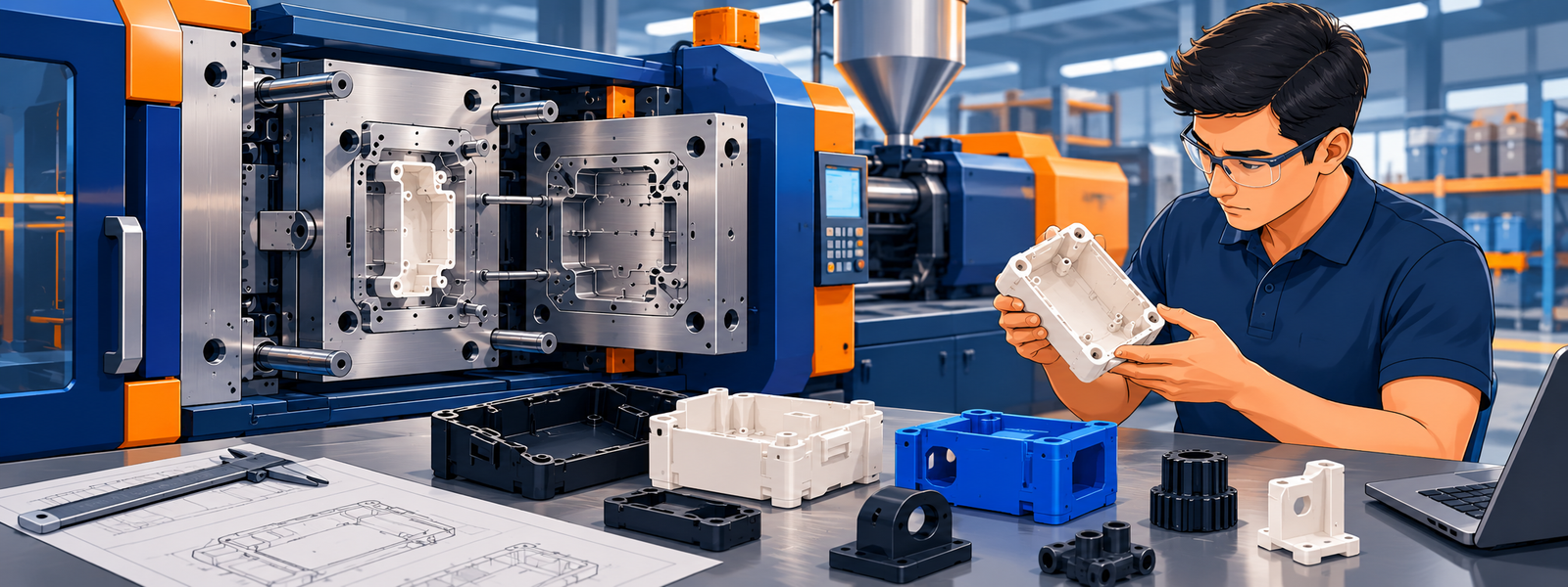
Prototype injection molding is used to produce functional plastic components using a mold built for product development, design validation or limited production. It helps engineering teams assess molded geometry, assembly interfaces, surface appearance and material performance before scaling to production tooling.
Unlike 3D printing, injection molding requires an upfront tooling investment. However, it can provide a more representative evaluation when the intended production material and molding process are important to the validation objective.
1. What Is Prototype Injection Molding?
Injection molding is a manufacturing process in which plastic material is heated, injected into a mold cavity, cooled and ejected as a finished component. In prototype injection molding, the mold is developed to support product validation, engineering trials or smaller production quantities.
Prototype tooling may use aluminum or steel. The right choice depends on geometry, material, required tool life, surface finish, expected quantity and the need for future modifications.
What can a molded prototype validate?
- Fit and assembly with adjoining components.
- Snap fits, clips, ribs, bosses and mounting interfaces.
- Material behavior under intended operating conditions.
- Part appearance, texture, color and surface finish.
- Potential sink marks, flash, warpage and molding defects.
- Repeatability of critical dimensions across a sample batch.
2. Applications of Prototype Injection Molding
Electronics and product enclosures
Molded prototypes help validate enclosure geometry, mounting bosses, connector openings, ventilation features and interfaces between housings and electronic assemblies.
Robotics and automation
Robotics developers may use molded prototypes for sensor housings, cable clips, covers, brackets and selected functional mechanisms. Material selection should reflect impact, wear, temperature and dimensional stability requirements.
Automotive and industrial components
Prototype molding supports evaluation of retainers, interior components, covers, protective housings and other plastic parts before tooling and production commitments are finalized.
Medical and laboratory equipment
Molded prototypes can be used for device housings, instrument components and non-implantable equipment parts. Applications involving patient contact, sterilization or regulated use require additional material qualification and validation.
The process is especially relevant when a team needs actual molded thermoplastic parts rather than a visual model alone.
3. How Prototype Injection Molding Works
Step 1: CAD and drawing review
Review the 3D model, 2D drawing, critical dimensions, wall thickness, draft, ribs, bosses, undercuts and functional interfaces. Resolve missing specifications before tooling.
Step 2: Design for manufacturability
Evaluate the parting line, gate location, ejection strategy, mold opening direction, side actions and expected shrinkage. Identify features that could complicate tooling or molding.
Step 3: Tool design and manufacture
Develop the mold using suitable tooling materials and machining processes. Slides, lifters, cavity count and finishing requirements influence tool complexity.
Step 4: Trial molding
Produce initial samples and evaluate filling, ejection, appearance, flash, sink marks, warpage and critical dimensions.
Step 5: Validation and corrections
Compare samples with the agreed requirements. Modify the mold or processing parameters where necessary and obtain approval before releasing the required quantity.
Step 6: Production and inspection
Manufacture the agreed batch, complete specified inspection and documentation, and coordinate packaging and dispatch.
4. Prototype Tooling Options
Prototype tooling should be selected according to the expected production quantity, part complexity, resin, acceptable development cost and likely design changes.
| Tooling approach | Typical consideration | Potential limitation |
|---|---|---|
| Aluminum prototype mold | Often suitable for development and selected low volume applications. | Wear resistance and durability depend on alloy, construction and process. |
| Steel prototype mold | May be appropriate for more demanding materials, tool life or features. | Machining and tooling costs may be higher. |
| Modified or bridge tooling | May support continued production while requirements evolve. | Existing tool design can restrict modifications or process optimization. |
Cavity count, cooling channels, mold base selection, surface finish, slides, lifters and insert requirements should all be considered when comparing tooling quotations.
Related reading: Explore the Manufyn Resource Hub for additional manufacturing and tooling knowledge.
5. Material Selection for Prototype Injection Molding
Material selection affects part strength, stiffness, impact resistance, chemical compatibility, shrinkage, processing conditions and cost. Select the specific resin grade based on application requirements rather than polymer name alone.
| Material | Common applications | Important considerations |
|---|---|---|
| ABS | Housings, covers and general functional parts | Grade-dependent impact performance, heat resistance and finish. |
| Nylon 6 / Nylon 66 | Clips, brackets, gears and mechanical components | Moisture absorption, conditioning and dimensional change. |
| Polycarbonate (PC) | Impact-resistant housings and selected transparent parts | Grade-specific chemical resistance and processing requirements. |
| Polypropylene (PP) | Lightweight components and chemical-resistant parts | Shrinkage, stiffness and warpage control. |
| POM | Selected gears, clips and moving components | Grade selection, dimensional stability and design compatibility. |
| TPU | Flexible components and protective features | Hardness, drying, flow and ejection requirements. |
| PEEK | High-performance engineering applications | High processing temperatures, tooling requirements and material cost. |
| PEI (Ultem) | Selected demanding thermal and engineering applications | Processing capability and grade-specific performance. |
Glass-filled materials require additional attention to fiber orientation, anisotropic shrinkage, warpage and gate positioning. Material drying and processing parameters must follow the selected resin manufacturer’s recommendations.
Related knowledge: Browse manufacturing materials and process guides.
6. Design for Manufacturability (DFM)
Design for manufacturability identifies potential tooling and molding problems before the mold is manufactured. Early DFM review can reduce revisions, avoid unnecessary complexity and improve the likelihood of obtaining acceptable samples.
Wall thickness
Maintain reasonably uniform wall thickness wherever practical. Sudden changes in section thickness can contribute to sink marks, voids, differential shrinkage and warpage.
Draft angles
Provide appropriate draft on surfaces parallel to the mold opening direction. The required draft depends on wall depth, resin, surface texture and tool finish.
Ribs and bosses
Use ribs to increase stiffness without introducing excessive local thickness. Review screw bosses, mounting features and load-bearing interfaces for adequate strength and moldability.
Undercuts and side actions
Features that prevent straight mold opening may require slides, lifters, collapsible mechanisms or design changes. These decisions can affect tooling cost, maintenance and lead time.
Gate location and weld lines
Gate placement influences filling, appearance, weld-line location and local mechanical performance. Discuss critical cosmetic and structural areas during the DFM review.
Shrinkage and warpage
Final dimensions depend on resin behavior, geometry, cooling, gate design and processing conditions. Avoid assuming that a dimension in the CAD model will transfer directly to the molded part without appropriate tool compensation and validation.
Further reading: Understand prototype cost drivers .
7. Injection Molding vs. Other Prototyping Processes
| Process | Best suited for | Main trade-off |
|---|---|---|
| Injection molding | Molded thermoplastic parts and repeatable batches | Requires tooling investment and mold development. |
| 3D printing | Early concepts, complex geometry and design iterations | Material properties and finish may differ from molded parts. |
| CNC machining | Precise prototypes and components made from solid stock | Geometry, machining access and material waste affect cost. |
| Urethane casting | Selected small batches made with silicone molds | Cast polyurethane is not equivalent to every production thermoplastic. |
For a single early-stage concept, 3D printing or CNC machining may be more economical. Injection molding becomes more relevant when the development objective requires molded material, representative geometry or repeated quantities.
Explore the related CNC prototype manufacturing guide to understand another common prototyping process and its finishing considerations.
8. Tolerances, Inspection and Quality Validation
Injection molded tolerances vary with part size, geometry, resin, tool construction and process stability. There is no single tolerance value that applies to every material and component.
Define the following before approving the prototype:
- Critical dimensions and geometric tolerances.
- Datum references and measurement methods.
- Material grade, filler content and color requirements.
- Acceptable flash, sink marks, weld lines and cosmetic defects.
- Assembly fit and functional acceptance criteria.
- Inspection records and material documentation.
Inspection methods may include calipers, micrometers, height gauges, optical measurement systems and CMM inspection, depending on the feature and required accuracy.
First article inspection and PPAP documentation may be required for specific customer or automotive programs. They should be agreed upon in advance rather than assumed necessary for every prototype.
Related article: Prototype inspection and dimensional verification .
9. What Affects Prototype Injection Molding Cost?
Total project cost includes tooling, molded parts, inspection, secondary operations and logistics. Unit price alone is not sufficient to compare quotations.
- Tool complexity: Cavity count, slides, lifters, inserts, cooling and finishing.
- Part geometry: Wall thickness, undercuts, complex features and dimensional requirements.
- Resin selection: Material price, drying requirements and processing conditions.
- Order quantity: Setup time, cycle time, scrap allowance and production volume.
- Quality requirements: Inspection scope, testing, reporting and documentation.
- Secondary operations: Drilling, trimming, assembly, inserts and special finishing.
- Logistics: Packaging, international freight, duties and delivery terms.
How to compare quotations
Ask suppliers to separate tooling cost, sample development, piece price at each quantity, inspection, packaging and shipping. Also clarify tool ownership, maintenance responsibility, expected tool life and charges for future modifications.
This makes it easier to compare prototype injection molding with CNC machining, 3D printing and other low volume manufacturing options using total project cost.
10. From Prototype Tooling to Low Volume Production
Prototype tooling may support limited production while a product is undergoing validation, demand testing or production planning. Whether the same tool should be retained depends on tool life, cycle time, dimensional consistency and expected order volumes.
- Design validation: Confirm geometry, material and critical features.
- Prototype samples: Evaluate dimensions, assembly, appearance and performance.
- Limited production: Establish the acceptable process and inspect the agreed batch.
- Production planning: Review demand, cycle time, tool life and cost per part.
- Production tooling: Invest in a production tool when the expected volume and economics justify it.
A prototype mold should not automatically be treated as a production mold. Review its construction and condition against the anticipated production requirements before scaling up.
11. Prototype Injection Molding RFQ Checklist
A complete request for quotation helps manufacturing suppliers assess tooling feasibility, material requirements, inspection scope and delivery expectations.
- 3D CAD model, preferably STEP or another agreed neutral format.
- 2D engineering drawing with dimensions and tolerances.
- Material grade, color and filler content.
- Prototype quantity and estimated annual or follow-on volume.
- Surface finish and cosmetic requirements.
- Critical dimensions and functional interfaces.
- Insert molding, secondary operations and assembly requirements.
- Inspection reports, material certificates or PPAP requirements, where applicable.
- Target delivery date and destination.
- Tool ownership, maintenance and future production expectations.
If the material or tooling strategy is not yet finalized, provide the application, operating conditions and target performance requirements so these can be evaluated during DFM.
13. Frequently Asked Questions
What is prototype injection molding used for?
It produces molded plastic parts for functional testing, design validation, assembly checks, appearance evaluation and selected low volume production applications.
Is prototype injection molding better than 3D printing?
Neither is universally better. Injection molding is useful when molded thermoplastic properties and repeatable batches matter. 3D printing is often preferable for early concepts, complex geometry and rapid design changes without tooling.
Which materials are suitable for molded prototypes?
Common materials include ABS, Nylon 6, Nylon 66, polycarbonate, polypropylene, POM, TPU, PEEK and PEI. Suitability depends on the exact grade, application and supplier’s processing capability.
Does prototype injection molding require a mold?
Yes. The process requires a mold cavity. Prototype tooling is generally selected to suit development requirements and expected quantities, rather than automatically using a high-volume production tool.
What files should I provide for a quotation?
Provide a 3D CAD model, 2D drawing, resin grade, quantity, tolerances, finish requirements and delivery destination. Include testing and inspection requirements where relevant.
Can prototype tooling be used for low volume production?
In suitable cases, yes. Confirm tool life, cycle time, process capability, dimensional consistency and maintenance needs before using prototype tooling for additional batches.
What determines the dimensional accuracy of a molded part?
Material shrinkage, part geometry, mold design, cooling, process stability and measurement conditions all influence dimensional accuracy. Critical tolerances should be agreed before tool manufacture.
Editorial note: Tooling choices, material suitability, tolerances and lead times should be confirmed against the specific component, resin grade, drawing and intended application.