Sheet metal fabrication is not a single process, it is a family of three distinct operation types: cutting, forming and joining. Within each family, multiple methods exist, each suited to a different combination of material, thickness, tolerance and production volume. Choosing the wrong method adds cost, reduces quality and extends lead time.
This guide covers every major method across all three families, with a decision table at the end so engineers and procurement managers can identify the right process for their specific part requirements.
Manufyn’s sheet metal fabrication service covers all methods listed in this guide, cutting, forming and joining, with free DFM review to confirm the right process for your part.
The Three Families of Sheet Metal Fabrication Methods
All sheet metal fabrication operations fall into one of three process families:
- Cutting methods, separate sheet metal into flat blank profiles
- Forming methods, change the shape of a blank without removing material
- Joining methods, connect formed components into assemblies
Most parts require all three families in sequence: a blank is cut, formed into shape, then joined if it is an assembly. Surface finishing sits outside these three families as a post-process applied to the completed part or assembly.
Cutting Methods: How Sheet Metal is Separated to Profile
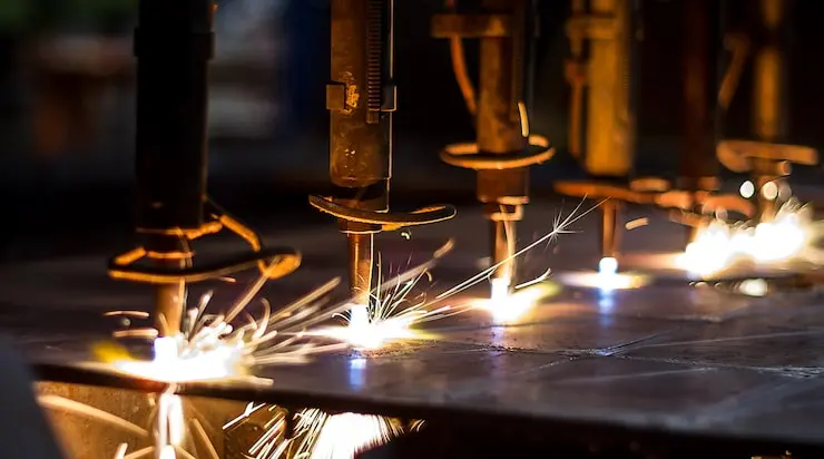
1. Fibre Laser Cutting
Fibre laser cutting uses a focused high-power laser beam (typically 2kW–12kW) to melt and vaporise sheet metal along a programmed CNC path. It is the most widely used cutting method in modern precision sheet metal fabrication.
| Parameter | Fibre Laser Specification |
|---|---|
| Materials | Mild steel, stainless steel, aluminium, copper, brass, titanium |
| Thickness | 0.5mm – 12mm (steel), 0.5mm – 8mm (aluminium), 0.5mm – 3mm (copper) |
| Tolerance | ±0.05mm positional, ±0.1mm overall part |
| Edge quality | Clean, low burr, no heat distortion on thin sheet |
| Setup | No tooling, programmed direct from DXF file |
| Lead time | Cut program ready in hours; no tool lead time |
| Best for | Complex profiles, tight tolerances, thin to medium gauge, prototypes to production |
Fibre laser cutting does not require physical tooling, making it ideal for prototypes and short runs where tooling investment is not justified. The absence of cutting force means delicate features and thin webs between holes are achievable without part distortion.
2. Plasma Cutting
Plasma cutting uses an electrically ionised gas jet (plasma) to melt and blow away metal along a CNC-programmed path. It is suited to thicker material where laser capability ends or where edge quality requirements are less critical.
| Parameter | Plasma Cutting Specification |
|---|---|
| Materials | All electrically conductive metals, mild steel, stainless, aluminium |
| Thickness | 3mm – 50mm+ (practical range for sheet metal work: 3mm – 25mm) |
| Tolerance | ±0.5mm – ±1.0mm (less precise than laser) |
| Edge quality | Heat-affected zone, some dross; secondary grinding required for tight fits |
| Setup | No tooling, CNC programmed |
| Best for | Thick structural plate, rough profile cuts, when laser capacity is insufficient |
3. Waterjet Cutting
Waterjet cutting uses a high-pressure jet of water (up to 90,000 PSI) mixed with an abrasive (garnet) to erode material along a CNC path. Because no heat is generated, it is the only cold-cutting process, essential for heat-sensitive materials.
| Parameter | Waterjet Specification |
|---|---|
| Materials | Any material, metals, composites, rubber, glass, ceramics, stone |
| Thickness | 0.5mm – 150mm+ depending on material |
| Tolerance | ±0.1mm – ±0.2mm |
| Edge quality | No heat-affected zone, smooth edge, no burr on metals |
| Setup | No tooling; slightly slower cut speed than laser |
| Best for | Titanium, hardened alloys, composites, multi-layer stacks, heat-sensitive parts |
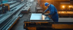
4. Shearing
Shearing uses a hardened blade pair to make straight-line cuts across sheet metal, similar to a very large pair of scissors. It is the fastest and cheapest way to cut rectangular blanks from coil or sheet.
| Parameter | Shearing Specification |
|---|---|
| Materials | Mild steel, aluminium, stainless steel, galvanised steel |
| Thickness | Up to 6mm depending on machine capacity |
| Tolerance | ±0.2mm – ±0.5mm |
| Edge quality | Clean cut, slight burr on bottom face |
| Constraint | Straight cuts only, no curves, no internal cut-outs |
| Best for | High-volume rectangular blanking; lowest cost per cut |
5. CNC Punching (Turret Punching)
CNC turret punching uses a library of standard punch-and-die toolsets mounted in a rotating turret. The CNC positions the sheet and the turret selects the correct tool to punch holes, slots and forms in a single setup.
| Parameter | CNC Punching Specification |
|---|---|
| Materials | Mild steel, stainless steel, aluminium, galvanised steel |
| Thickness | 0.5mm – 6mm |
| Tolerance | ±0.1mm hole position, ±0.1mm diameter |
| Capability | Holes, slots, louvers, countersinks, dimples, embosses from standard tooling |
| Best for | High hole count parts, volume production, parts combining holes + formed features |
| Vs laser | Lower cost per hole at high volume; limited to standard tool shapes |
Forming Methods: How Sheet Metal is Shaped
6. CNC Press Brake Bending
Press brake bending is the most common forming operation in sheet metal fabrication. A hydraulic or servo-electric press forces a hardened punch into a V-die to create a precise bend at a defined angle and radius.
| Parameter | Press Brake Specification (Manufyn) |
|---|---|
| Materials | All sheet metals up to 12mm thickness |
| Angular tolerance | ±0.1° per bend |
| Linear tolerance | ±0.1mm flange length |
| Min bend radius | 1× thickness (mild steel) / 1.5× (6061 aluminium) |
| Max sheet size | 3,000mm × 1,500mm |
| Max force | 220 tonnes |
| Best for | Brackets, enclosures, panels, chassis, any part with angular bends |
7. Roll Forming and Rolling
Rolling passes sheet metal through a series of profiled rollers that progressively bend the sheet into a curved cross-section. It is used for cylinders, cones, curved panels and structural sections.
- Plate rolling, cylinders, cones, curved enclosure panels from flat sheet
- Roll forming, continuous extrusion-like process for structural profiles (channels, angles, tubes) from coil
- Best for curved parts that cannot be achieved with press brake bending.
8. Stamping
Stamping uses a matched punch-and-die set to form, cut and pierce sheet metal in a single press stroke. It is a high-volume process, the tooling investment is recovered over large production quantities
| Parameter | Stamping Specification |
|---|---|
| Materials | Mild steel, aluminium, stainless steel, copper, brass |
| Thickness | 0.3mm – 6mm (typical for precision stampings) |
| Tolerance | ±0.05mm – ±0.1mm with good tooling |
| Tooling cost | £2,000 – £30,000+ depending on complexity |
| Volume break-even | Typically 500–2,000 pieces minimum for tooling ROI |
| Best for | High-volume identical parts: brackets, clips, terminals, covers |
9. Deep Drawing
Deep drawing pulls a flat blank into a die cavity using a punch, forming a seamless cup or shell without a weld seam. It is used for cylindrical, rectangular and irregular containers where a welded assembly would not meet strength or seal requirements.
- Applications: enclosures without corner welds, battery casings, medical device cups, oil filters
- Materials: mild steel, aluminium, stainless steel, copper
- Advantage: no weld seam, improves strength, eliminates weld inspection, reduces finishing cost
Joining Methods: How Sheet Metal Components are Assembled
10. MIG Welding (GMAW)
Metal Inert Gas (MIG) welding feeds a continuous wire electrode into the weld pool while shielding gas prevents oxidation. It is the fastest and most cost-effective welding process for general sheet metal assemblies.
| Parameter | MIG Welding (GMAW) |
|---|---|
| Materials | Mild steel, stainless steel, aluminium (with appropriate wire + gas) |
| Thickness | 0.8mm – 12mm (sheet metal range) |
| Weld quality | Structural grade; bead appearance good but not cosmetic |
| Speed | Fastest arc welding process |
| Best for | Structural assemblies, HVAC, enclosures, general fabrication |
11. TIG Welding (GTAW)
Tungsten Inert Gas (TIG) welding uses a non-consumable tungsten electrode and optional filler rod to produce the highest quality welds in sheet metal fabrication. It is slower than MIG but produces cosmetically superior welds.
| Parameter | TIG Welding (GTAW) |
|---|---|
| Materials | Aluminium, stainless steel, titanium, thin mild steel, dissimilar metals |
| Thickness | 0.5mm – 6mm (ideal range for TIG on sheet) |
| Weld quality | Cosmetic grade, smooth bead, minimal spatter, no undercut |
| Speed | Slowest arc welding process |
| Best for | Visible welds, aluminium, precision assemblies, medical/food grade stainless |
12. Spot Welding (Resistance Welding)
Spot welding passes electrical current through two copper electrodes that clamp overlapping sheets together, generating resistance heat to fuse the sheets at a discrete point. It produces flush joints with no added material.
- No filler wire, weld is flush on both faces
- Extremely fast, cycle time under 1 second per spot
- Best for sheet-to-sheet lap joints in mild steel and galvanised steel
- Common in automotive body assembly, HVAC plenums, electrical enclosures
13. Riveting and Blind Riveting
Riveting joins sheet metal where welding is impractical, dissimilar materials, painted surfaces, or joints that must be disassembled. Blind rivets (pop rivets) are installed from one side only, useful where rear access is impossible.
- Blind rivets, installed from one side; used in enclosures, panels, access doors
- Structural rivets, higher shear strength; used in aerospace secondary structure
- Rivet nuts, installed in thin sheet to provide a threaded hole for bolt assembly
14. Hardware Insertion (PEM Fasteners)
Press-in or weld-on hardware (PEM nuts, standoffs, studs, panel fasteners) is inserted into sheet metal to provide strong threaded points without welding. This is standard practice for electronics enclosures and equipment panels where multiple disassemblies are required.
- PEM nuts, pressed into punched holes to provide M3–M12 threads in thin sheet
- Weld nuts, resistance-welded to sheet back face for higher pull-out strength
- Captive screws, quarter-turn fasteners for access panels
- Installed before surface finishing to protect threads from coating fill
Comparison Table: All Sheet Metal Fabrication Methods
| Parameter | Fibre Laser Specification |
|---|---|
| Materials | Mild steel, stainless steel, aluminium, copper, brass, titanium |
| Thickness | 0.5mm – 12mm (steel), 0.5mm – 8mm (aluminium), 0.5mm – 3mm (copper) |
| Tolerance | ±0.05mm positional, ±0.1mm overall part |
| Edge quality | Clean, low burr, no heat distortion on thin sheet |
| Setup | No tooling, programmed direct from DXF file |
| Lead time | Cut program ready in hours; no tool lead time |
| Best for | Complex profiles, tight tolerances, thin to medium gauge, prototypes to production |
Decision Guide: Which Method Does My Part Need?
| If your part requires… | Use this method |
|---|---|
| Complex curved profile in steel/aluminium | Fibre laser cutting |
| Thick plate (>12mm) with rough profile | Plasma cutting |
| Heat-sensitive alloy (titanium, Inconel) | Waterjet cutting |
| High-volume rectangular blanks | Shearing |
| Dense hole patterns in volume | CNC punching |
| Angular bends (brackets, enclosures) | Press brake bending |
| Cylindrical or curved shape | Rolling |
| High-volume identical formed parts | Stamping |
| Seamless cup / container without weld seam | Deep drawing |
| Structural welded assembly, mild/SS steel | MIG welding |
| Visible weld, aluminium, thin material | TIG welding |
| Sheet-to-sheet lap joint at volume | Spot welding |
| Dissimilar materials, one-side access | Blind riveting |
| Threaded points in thin sheet | PEM hardware insertion |
Not sure which process your part needs? Send your drawing to Manufyn’s engineers for a free DFM review, we advise on the optimal method combination and confirm manufacturability before quoting.
Frequently Asked Questions
A: Sheet metal fabrication methods are grouped into three families: cutting (fibre laser, plasma, waterjet, shearing, CNC punching), forming (press brake bending, rolling, stamping, deep drawing), and joining (MIG welding, TIG welding, spot welding, riveting, PEM hardware insertion). Most parts use a combination of methods from all three families.
A: Fibre laser cutting combined with CNC press brake bending is the most common combination in modern sheet metal fabrication. Laser cutting produces the flat blank profile, and press brake bending forms it into the three-dimensional shape. This combination covers the majority of enclosures, brackets, panels and structural components.
A: Fibre laser cutting achieves the tightest tolerances of all cutting methods, ±0.05mm positional accuracy. Waterjet cutting follows at ±0.1mm. CNC punching and shearing are in the ±0.1–0.2mm range. Plasma cutting is the least precise at ±0.5–1mm and is used for structural work where tight tolerances are not required.
A: Aluminium sheet metal can be processed by all cutting methods (laser is preferred for clean edges), press brake bending (minimum bend radius is 1.5× thickness for 6061-T6), rolling, stamping, deep drawing, TIG welding (preferred over MIG for cosmetic welds), MIG welding (with 4043 or 5356 wire), and riveting. Aluminium does not spot weld as reliably as steel and requires appropriate tooling and gas mix for TIG/MIG.
A: These terms are often used interchangeably. ‘Method’ typically refers to the specific operation within a family (e.g., laser cutting is a method within the cutting family). ‘Process’ more often refers to the end-to-end production sequence, the eight-stage flow from drawing review to dispatch. In practice, engineers use both terms to mean the specific operation applied to their part.
Need sheet metal parts fabricated?
Manufyn is India’s ISO 9001 certified sheet metal fabrication manufacturer, serving the US, UK, Australia, UAE and 30+ countries.
Quote in 24 hours. No minimum order.
Get an Instant Quote
WhatsApp: +91 84840 32262 | Email: info@manufyn.com
ISO 9001 · 24-Hr Quote · No MOQ · 5-Day Prototypes · Free DFM · 30+ Countries