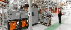
Sheet Metal Fabrication Process: Step-by-Step Guide
The sheet metal fabrication process is an eight-stage production sequence that converts a flat metal sheet into a finished, surface-treated part or assembly. It begins with a DXF, STEP or PDF drawing and ends with dimensionally inspected parts packaged and dispatched to your facility. Understanding each stage helps engineers design better parts, write tighter procurement briefs, and set realistic lead time expectations.
Manufyn’s sheet metal fabrication process service covers all eight stages in-house, from drawing review through to surface finish and dispatch. Free DFM review on every quote.
What is the sheet metal fabrication process?
The sheet metal fabrication process starts with a customer drawing (DXF, STEP, IGES or PDF), moves through DFM review, material procurement, cutting, forming, joining, surface finishing, and dimensional inspection, before parts are packaged and shipped. Each stage is interdependent, a decision at the design stage directly affects cost, lead time and quality at every subsequent stage.
The Eight Stages of Sheet Metal Fabrication
Stage 1: Drawing Review and DFM Analysis
Every Manufyn order begins with a complete review of the customer’s drawing package. The engineering team checks for:
- Completeness, all views, dimensions and tolerances called out
- Material specification, grade, thickness, temper
- Finish specification, colour, coating, standard reference
- Quantity and delivery requirement, prototype vs production
- File format integrity, DXF curves are arcs not polylines, STEP geometry is watertight
DFM (Design for Manufacturability) analysis runs concurrently. Common issues flagged at this stage include:
- Bend radius smaller than 1x material thickness (causes cracking)
- Holes placed too close to a bend line (distortion during forming)
- Sharp internal corners requiring impossible tooling radii
- Inconsistent wall thickness across a single part
- Tolerances tighter than the process can achieve (increases cost without benefit)
Manufyn’s engineers document all DFM flags and send a report back before quoting. This avoids costly rework after production has started. DFM review is provided free on every order.
Stage 2: Quotation and Order Confirmation
Once the drawing is reviewed and DFM issues resolved, a detailed quote is issued within 24 hours. The quote includes a line-by-line breakdown:
| Quote Line Item | What It Covers |
|---|---|
| Material cost | Grade, thickness, weight per part × quantity + scrap factor |
| Cutting cost | Laser or plasma time, nesting efficiency, number of cuts |
| Forming cost | Number of bends × setup + run time per bend |
| Welding cost | Weld length × process rate (MIG, TIG, spot) |
| Finishing cost | Powder coat, anodising, plating, by surface area |
| Inspection cost | FAIR, CMM report, dimensional check sheets |
| Packaging & freight | Export carton, pallet, air or sea freight to destination |
| Lead time | Working days from drawing approval to dispatch |
After the customer approves the quote and drawings, an NDA is signed if required, tooling ownership is documented, and production is scheduled.
Stage 3: Material Sourcing and Certification
Manufyn sources certified mill material for every order. Material is not held speculatively, it is procured per order to guarantee traceability. For each material type:
| Material | Standard | Certification Provided |
|---|---|---|
| Aluminium 6061-T6 | ASTM B209 / EN 573 | Mill test certificate on request |
| Stainless Steel 304 | ASTM A240 / EN 10088 | Mill cert + heat/lot number |
| Stainless Steel 316 | ASTM A240 / EN 10088 | Mill cert + chemical analysis |
| Mild Steel DC01 | EN 10130 | Mill cert + mechanical properties |
| Galvanised Steel G90 | ASTM A653 / EN 10346 | Zinc coating weight cert |
| Copper C101 | ASTM B152 / EN 1652 | Mill cert + conductivity data |
| Titanium Grade 2 | ASTM B265 | Full mill cert + certs of conformance |
Material certificates are retained in the job file and provided to the customer on request. This is essential for aerospace, medical and defence applications where full material traceability is a qualification requirement.
Stage 4: Cutting
Cutting converts the raw sheet into a flat blank profile matching the unfold geometry of the part. At Manufyn, four cutting technologies are available:
| Process | Thickness Range | Tolerance | Best Application |
|---|---|---|---|
| Fibre Laser | 0.5mm – 12mm | ±0.05mm | Complex profiles, tight tolerances, clean edge finish |
| Plasma | 3mm – 50mm+ | ±0.5mm | Thick structural plate, rough profile cuts |
| Waterjet | 0.5mm – 150mm | ±0.1mm | Heat-sensitive alloys, composites, multi-layer stacks |
| Shearing | Up to 6mm | ±0.2mm | Straight-line blanks at high volume, lowest cost |
| CNC Punching | 0.5mm – 6mm | ±0.1mm | Hole patterns, slots, embossed forms in volume |
Fibre laser cutting is the standard process for most orders. The fibre laser CNC program is generated directly from the customer DXF, no hand programming, no geometric interpretation. Nesting software maximises material yield to minimise waste and reduce per-part material cost.
Stage 5: Forming, CNC Press Brake Bending
Forming converts the flat cut blank into its three-dimensional shape. CNC press brake bending is the primary forming process at Manufyn.
The CNC brake program is generated from the 3D model (STEP) using K-factor compensation for each material and thickness. This ensures the bend line falls in the correct position after springback. Key process parameters:
| Parameter | Typical Achievable Value |
|---|---|
| Angular tolerance | ±0.1° per bend |
| Linear (flange) | ±0.1mm |
| Minimum bend radius | 1× material thickness (mild steel), 1.5× (aluminium 6061) |
| Maximum sheet size | Up to 3,000mm × 1,500mm |
| Maximum forming force | 220 tonnes |
For parts with more than four bends, a step-by-step bend sequence is programmed to ensure each bend is accessible without interference from previously formed flanges. Complex brackets and enclosure bodies with six to twelve bends are a standard Manufyn capability.
Other forming operations available alongside press brake bending:
- Roll forming, curved panels, cylinders, cones
- Stamping, high-volume formed features (embosses, dimples, louvers)
- Deep drawing, seamless cups, shells, tanks
Stage 6: Joining, Welding, Riveting and Hardware Insertion
After forming, individual sheet metal components are joined into assemblies. Manufyn operates a full welding facility supporting:
| Process | Application | Typical Weld Quality |
|---|---|---|
| MIG (GMAW) | Mild steel, stainless steel, aluminium assemblies | Structural, good bead appearance |
| TIG (GTAW) | Thin material, aluminium, precision joints, cosmetic welds | Highest quality, slowest |
| Spot Welding | Sheet-to-sheet lap joints at volume | Fast, no filler, flush both sides |
| Stud Welding | Attaching threaded studs to sheet faces | Strong base, no back-face marking |
| Seam Welding | Continuous leak-proof joints for tanks, plenums | Pressure-rated seams |
Hardware insertion (PEM nuts, threaded inserts, standoffs, captive fasteners) is carried out before surface finishing to protect threads from powder coat or anodising fill. Manufyn specifies PEM or equivalent hardware per customer drawing callout.
Manufyn handles all eight stages of the sheet metal fabrication process in-house, get a
Stage 7: Surface Finishing
Surface finishing serves two purposes: corrosion protection and aesthetics. The correct finish depends on the operating environment, appearance requirements and budget. Manufyn’s finishing options:
| Finish | Process | Thickness/Build | Best For |
|---|---|---|---|
| Powder Coat | Electrostatic spray + cure | 60–80 microns | General industrial, any RAL colour |
| Anodise Type II | Electrochemical bath | 5–25 microns | Aluminium, decorative, corrosion |
| Anodise Type III | Hard anodise | 25–50 microns | Aluminium, wear resistance |
| Zinc Electroplate | Electrochemical | 5–25 microns | Mild steel corrosion protection |
| Chrome Plate | Electrochemical | 0.5–2 microns | Decorative + hardness |
| Passivation | Acid treatment | Surface treatment | Stainless steel weld zones |
| Brushing / Blast | Mechanical abrasion | Surface texture | Cosmetic panels, enclosures |
| Bare/Degreased | Solvent clean only | None | Customer paints post-assembly |
All powder coat is applied to RAL or Pantone reference unless a custom colour chip is provided. Colour standards are maintained per batch and documented in the quality record. For aluminium anodising, the anodise class (clear, black, custom colour) and film thickness are specified on the drawing or purchase order.
Stage 8: Quality Inspection and FAIR
Every Manufyn order is dimensionally inspected before dispatch. The inspection scope depends on the order type:
| Order Type | Inspection Method | Documentation Issued |
|---|---|---|
| Prototype (1–10 pcs) | 100% dimensional check | First Article Inspection Report (FAIR) |
| Small batch (10–100) | Statistical sampling (AQL) | Inspection report with measurement data |
| Production run | AQL 1.5 sampling plan | Certificate of Conformance + batch records |
| Aerospace / Medical | 100% CMM inspection | Full CMM report + FAIR + material certs |
The First Article Inspection Report (FAIR) documents every critical dimension against the drawing with actual measured values, measurement method, and pass/fail status. FAIR is issued as standard on all prototype orders and on the first production batch of any new part number.
Non-conformances identified during inspection are either reworked in-station (if feasible within tolerance) or escalated to the customer with a corrective action report. No non-conforming parts are dispatched without written customer concession.
Stage 9: Packaging and Dispatch
Sheet metal parts are susceptible to surface damage in transit. Manufyn’s standard packaging protocol:
- Individual parts wrapped in VCI (volatile corrosion inhibitor) poly bag where material requires protection
- Formed parts separated by foam or cardboard interleaves to prevent edge-to-surface contact
- Assemblies bubble-wrapped individually then packed in double-wall export carton
- Fragile parts or tight-tolerance assemblies packed in custom foam-cut inserts
- Pallet wrap and corner protection applied for sea freight consignments
Freight options from Manufyn’s facility to international destinations:
| Destination | Air Freight | Sea Freight (LCL) | Recommended For |
|---|---|---|---|
| UK | 3–5 working days | 25–30 days | Air for prototypes, sea for production |
| USA | 4–6 working days | 28–35 days | Air for urgent, sea for volume |
| Australia | 5–7 working days | 18–22 days | Air for samples, sea for production |
| UAE | 1–2 working days | 3–5 days | Air cost-effective given proximity |
| Germany | 3–4 working days | 25–28 days | Air for prototypes |
| Canada | 5–7 working days | 30–35 days | Air for prototypes, sea for bulk |
All shipments are tracked end-to-end. Manufyn provides the commercial invoice, packing list, certificate of origin (for import duty purposes) and material certificates as part of the standard shipping documentation package.
Have a question about your specific project? Send your drawing to our engineers and we will respond within 4 hours.
Common Sheet Metal Fabrication Process Questions
A: The sheet metal fabrication process follows eight stages:
(1) Drawing review and DFM analysis,
(2) Quotation and order confirmation,
(3) Material sourcing with certification,
(4) Cutting (laser, plasma, waterjet or shearing),
(5) Forming by CNC press brake bending,
(6) Joining by welding, riveting or hardware insertion,
(7) Surface finishing (powder coat, anodise, plate),
(8) Quality inspection and dispatch.
At Manufyn, all eight stages are performed in a single facility with a 24-hour quote turnaround.
A: Prototype orders (1–10 pieces) typically take 5–10 working days from drawing approval to dispatch. Small production batches (10–100 pieces) take 10–15 working days. High-volume production runs are quoted with lead times based on capacity scheduling at order confirmation. Air freight to the US, UK and Australia adds 4–6 working days to in-hands lead time.
A: Manufyn accepts DXF, DWG, STEP, IGES, SolidWorks (.sldprt, .sldasm), Inventor (.ipt, .iam), CATIA V5, and PDF drawings with dimensions. For laser cutting, DXF is preferred. For 3D forming, STEP is preferred. PDF drawings with complete 2D views and dimensions are accepted for all processes.
A: Design for Manufacturability (DFM) is the practice of reviewing a part design before production to identify features that are difficult, costly or impossible to manufacture. In sheet metal fabrication, DFM catches issues like undersized bend radii, holes too close to bend lines, and unnecessarily tight tolerances, all of which increase cost or cause quality problems. Manufyn provides DFM review free on every quote.
A: For a prototype order at Manufyn: upload your drawing, receive a 24-hour quote with DFM feedback, approve and confirm the order, Manufyn sources certified material, cuts, forms, welds and finishes the parts, performs 100% dimensional inspection, issues a FAIR report, and dispatches by air freight with full tracking. Typical prototype cycle time is 5–10 working days from drawing approval.
Need sheet metal parts fabricated?
Manufyn is India’s ISO 9001 certified sheet metal fabrication manufacturer, serving the US, UK, Australia, UAE and 30+ countries.
Quote in 24 hours. No minimum order.
Get an Instant Quote
WhatsApp engineers: +91 84840 32262 Email: info@manufyn.com
ISO 9001 Certified · 24-Hr Quote · No MOQ · 5-Day Prototypes · 30+ Countries