Choose the right finish with Manufyn’s machining expertise
CNC surface finish defines the texture and smoothness left behind on a machined part after cutting operations. It affects how components fit, seal, slide, and appear in final assemblies. Every tool, feed rate, material, and process choice influences the resulting finish, so engineers must understand which finishes are achievable and which are necessary for functional performance.
Well-selected CNC surface finish requirements improve product reliability while preventing unnecessary cost. Standard machining finishes often work for non-critical geometry, but precision interfaces, cosmetic faces, and sealing surfaces may require tighter roughness values or secondary processes.
This guide outlines the essential concepts, standard ranges, process capabilities, and practical considerations engineers need to specify surface finish correctly and consistently.
What Is Machining Surface Finish?
Machining surface finish represents the microscopic peaks and valleys left on a part after cutting. It is measured primarily using Ra (Roughness Average) or Rz (Peak-to-Valley Height). Ra is the most common specification because it provides a consistent indication of surface smoothness across most CNC operations.
Surface finish matters because it directly impacts friction, sealing performance, wear behavior, and cosmetic quality. A rough surface may cause leaks, noise, premature wear, or poor fit. Conversely, over-specifying machining surface finish increases machining time and cost without delivering functional benefit.
Understanding roughness values and how they correlate to cutting methods enables engineers to assign surface finish requirements that balance performance and manufacturability.
Factors That Influence Machining Surface Finishes
Several interacting variables shape machining surface finishes, and even small changes in machining parameters can shift the resulting roughness. To begin with, cutting tool condition significantly affects finish quality. Sharp tools and larger corner radii produce smoother surfaces, whereas worn tools increase tearing and micro-chatter.
Additionally, feed rate and step-over directly affect surface texture. Higher feed rates leave visible tool marks, while reduced step-overs and slower finishing passes improve surface uniformity. Material behavior also plays a critical role. For example, aluminum and brass machines cleanly, while stainless steel, titanium, and plastics require careful control to avoid heat-induced or mechanical deformation.
Furthermore, the toolpath strategy affects consistency across the surface. Continuous, uniform paths—especially climb milling—tend to deliver better finishes. Abrupt direction changes or aggressive entry moves can introduce irregular marks. Finally, machine rigidity, spindle condition, coolant flow, and chip evacuation all contribute to surface stability by minimizing vibration and heat buildup during cutting.
Key Influencers:
- Tool sharpness and corner radius
- Feed rate, step-over, and finishing passes
- Material machinability and thermal behavior
- Toolpath style (climb vs. conventional)
- Machine rigidity and spindle stability
- Coolant flow and chip evacuation
Standard Machining Surface Finish
A standard machining surface finish refers to the roughness achieved during typical CNC milling or turning without special optimization. Generally, most shops deliver finishes in the range of Ra 1.6–3.2 µm for milling and Ra 0.8–1.6 µm for turning when no specific value is requested. These values represent a practical balance between machining efficiency and acceptable surface quality.
In most cases, a standard machining surface finish is suitable for non-critical areas such as structural faces, internal cavities, and general mounting surfaces. Engineers should avoid specifying extremely tight finishes unless they are functionally necessary.
Otherwise, tighter finishes may require slower feeds, additional passes, improved tooling, or even secondary finishing processes like grinding or polishing—all of which increase cost and lead time.
Standard finish is appropriate for:
- Non-sealing surfaces
- Hidden or internal features
- Brackets, frames, and structural components
- General-purpose mating areas
CNC Machining Surface Finish Chart
Surface roughness requirements vary depending on the machining method and functional needs of the part. Therefore, engineers often reference standardized Ra values to determine what is achievable through milling, turning, or secondary finishing. The following machining surface finish chart provides a concise overview of common roughness ranges and the processes typically used to achieve them.
CNC Surface Finish Chart (Ra µm)
| Ra (µm) | Description | Typical Process | Common Applications |
|---|---|---|---|
| 6.3 – 3.2 | Standard rough finish | Rough milling, turning | Non-critical surfaces, structural parts |
| 3.2 – 1.6 | General machining finish | Standard milling, turning | Mounting faces, enclosures |
| 1.6 – 0.8 | Fine machining finish | Finishing passes, sharp tools | Sliding parts, lightly loaded interfaces |
| 0.8 – 0.4 | Precision machining finish | High-speed machining, controlled feed | Sealing faces, light bearing fits |
| 0.4 – 0.2 | Very fine finish | Precision turning, reaming | Hydraulic parts, tight tolerance bores |
| 0.2 – 0.1 | Ultra-fine finish | Grinding, honing | Precision shafts, bearing surfaces |
| < 0.1 | Mirror-like finish | Lapping, polishing | Optical components, high-wear surfaces |
As a result, this chart makes it easier to select a surface finish early in the design phase and verify that the chosen machining process can achieve the required roughness.
Surface Finish Requirements by Process
Different machining processes produce different surface textures due to cutting mechanics, tooling, and toolpath characteristics. Consequently, engineers should align their surface finish requirements with the strengths and limitations of each process.
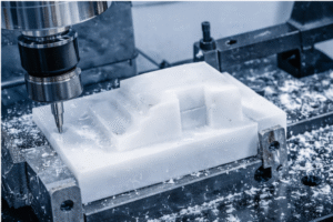
1. CNC Milling
Milling typically produces finishes between Ra 3.2–1.6 µm, depending on tool geometry and feed strategy. However, achieving finer finishes requires slower feed rates and optimized step-overs. Finishing passes with sharp tools or high-speed machining routines can improve consistency, especially on aluminum.
Typical Range: Ra 3.2–0.8 µm
Best For: Flat surfaces, pockets, cosmetic faces
Limitations: Tool deflection affects finish on tall walls and deep pockets
2. CNC Turning
Turning generally yields smoother finishes than milling due to continuous tool engagement. Standard turning achieves Ra 1.6–0.8 µm, while precision turning can reach Ra 0.4 µm or better. Therefore, turning is preferred for shafts, cylindrical features, and sealing diameters.
Typical Range: Ra 1.6–0.4 µm
Best For: Shafts, bores, concentric features
Limitations: Interrupted cuts reduce finish quality
3. 5-Axis CNC Machining
5-axis machining allows optimal tool orientation, which improves surface consistency across complex surfaces. Finishes typically fall between Ra 1.6–0.8 µm, depending on geometry and material.
Best For: Contoured surfaces, multi-face features
Limitations: Machine calibration affects micro-finish accuracy
4. Secondary Finishing Processes
When machining alone cannot achieve the required roughness, secondary processes provide enhanced accuracy.
Common options:
- Grinding: Ra 0.2–0.1 µm
- Honing: Ra 0.1 µm or better
- Polishing/Lapping: < Ra 0.05 µm
- Bead blasting: Uniform matte texture (not a roughness control method)
In summary, secondary processes are ideal when functional or cosmetic demands exceed standard machining capability.
Surface Finish Requirements by Function
Surface finish requirements vary significantly depending on how a part functions in an assembly. As a result, engineers should link roughness values to performance needs rather than applying one tolerance across the entire part. The table below summarizes typical finish expectations for common functional surfaces.
Functional Surface Finish Requirements (Ra µm)
| Function | Recommended Ra (µm) | Reasoning |
|---|---|---|
| Sliding surfaces | 0.8 – 0.4 | Reduces friction and wear; smoother surfaces improve motion stability |
| Sealing faces | 0.8 – 0.2 | Prevents leakage; ensures gasket or O-ring compression seals evenly |
| Bearing seats & precision fits | 0.4 – 0.1 | Requires tight geometric and surface control for proper load distribution |
| Load-bearing joints | 1.6 – 0.8 | Allows stable contact without requiring ultra-fine finish |
| Cosmetic surfaces | 1.6 – 0.8 (machined) or smoother via finishing | Appearance-driven; may require polishing, brushing, or bead blasting |
| General structural surfaces | 3.2 – 1.6 | No functional dependence on roughness; standard machining is sufficient |
Therefore, selecting finish based on function ensures the part performs reliably while avoiding unnecessary cost associated with over-tightening surface requirements.
How to Specify CNC Surface Finish on Drawings
Specifying surface finish correctly on drawings ensures consistent interpretation across machinists, programmers, and inspectors. Clear, measurable values prevent ambiguity and reduce manufacturing variation.
1. Use Ra Values for Clarity
Surface finish should always be specified using Ra (Roughness Average) values—such as Ra 1.6 µm—directly on the surfaces where the requirement applies. This eliminates vague instructions like “smooth finish,” which different shops may interpret differently.
2. Apply Finish Only Where Function Requires It
Over-specifying finish on non-critical surfaces increases cost and inspection time. Apply tight finishes only to:
- Sealing faces
- Sliding interfaces
- Cosmetic-visible faces
- Precision fits
Leave general surfaces under the standard shop finish when possible.
3. Add Supporting Notes When Needed
Certain finishes require clarification on:
- Process (e.g., “polish to Ra 0.4 µm”)
- Measurement method (profilometer, comparator gauge)
- Post-process final condition (“finish required after anodizing”)
These notes help manufacturers produce the correct final texture.
4. Include GD&T Only When Functionally Necessary
Surface finish influences flatness, waviness, and positional accuracy. When these factors matter, relevant GD&T symbols can be included. However, GD&T should not be used as a substitute for surface finish values.
Best Practices for Achieving Consistent Surface Finish
Producing consistent surface finish requires optimizing machining parameters, maintaining tool health, and selecting appropriate tooling and strategies. The following best practices help achieve stable, repeatable texture across batches.
1. Use Sharp Tools and Dedicated Finishing Passes
Tool sharpness significantly affects finish quality. Worn tools introduce micro-chatter and tearing. A dedicated finishing tool or pass—with reduced step-over and low feed per tooth—improves uniformity and reduces tool marks.
2. Optimize Speeds, Feeds, and Step-Over
Feed rate, spindle speed, and step-over heavily influence roughness.
- Lower feed → smoother texture
- Smaller step-over → reduced tool marks
- Consistent finishing pass → stable overall Ra
For milling, climb cutting typically produces smoother surfaces due to better chip formation.
3. Improve Coolant and Chip Evacuation
Heat and recutting of chips are major contributors to rough surfaces. High-pressure coolant or air blast ensures clean chip removal and prevents heat buildup, especially in stainless steel, titanium, and plastics.
4. Consider Material Behavior Early
Some materials inherently produce better finishes:
- Aluminum, brass → excellent finish potential
- Stainless steel, titanium → require conservative parameters
- Plastics → sensitive to heat and tool geometry
Match finish expectations to material capability.
5. Ensure Proper Fixturing and Machine Stability
Rigid setups reduce vibration, which directly improves surface finish. Shorter tool stickout, stable datums, and high-speed spindles contribute to cleaner surfaces and reduce finishing time.
6. Choose Suppliers With Proven Finish Capability
Not all shops achieve the same micro-finish consistency. Supplier experience, machine calibration, and tooling systems influence the result.
Therefore, selecting a supplier with demonstrated surface finish capability ensures repeatability across batches.
Common Surface Finish Defects & How to Prevent Them
Surface finish defects occur when machining parameters, tooling, or material conditions deviate from optimal settings. Identifying the root cause early prevents defects from recurring across batches.
1. Chatter Marks
Chatter creates visible, wave-like patterns on the surface. It originates from vibration due to inadequate rigidity, incorrect feed/speed selection, or excessive tool overhang.
Prevention:
- Shorten tool stickout
- Strengthen fixturing
- Adjust speeds/feeds to avoid resonance
- Use variable-helix tools
2. Tool Marks and Step-Over Lines
Visible machining lines often occur when feed rates are too high or step-over is too large during finishing passes.
Prevention:
- Reduce step-over for finishing
- Use a dedicated finishing tool
- Lower feed per tooth
- Apply high-speed machining toolpaths
3. Burr Formation
Burrs form when cutting forces push material outward instead of shearing it cleanly. Soft metals and plastics are especially prone to this defect.
Prevention:
- Use sharper tools
- Optimize entry/exit toolpaths
- Employ deburring tools or micro-finishing passes
- Consider chamfering at edges
4. Heat-Induced Roughness
Discoloration, rough patches, or smeared surfaces appear when the material overheats. This is common in stainless steel, titanium, and plastics.
Prevention:
- Improve coolant delivery
- Reduce cutting speed
- Increase chip evacuation
- Use coatings that reduce friction
5. Inconsistent Finish Across the Part
Changes in roughness across the same surface indicate instability in tool wear, feed rate, or machine setup.
Prevention:
- Use consistent finishing parameters
- Inspect tool before finishing
- Add toolpath smoothing
- Avoid mid-surface tool engagement changes
Cost & Lead-Time Impact of Surface Finish Requirements
Surface finish requirements directly affect machining cost, time, and feasibility. Tighter finishes require slower machining parameters and additional tool passes, increasing overall production effort. For example, moving from Ra 3.2 µm to Ra 0.8 µm may require multiple finishing passes, higher-quality tooling, and stricter process control.
1. When Tighter Finishes Increase Cost
Costs rise significantly when finish requirements exceed standard machining capability. The following conditions often trigger cost increases:
- Extremely small step-overs
- Low feed rates for finishing
- Advanced tooling or coatings
- Additional inspection steps
- Secondary finishing processes
- Reduced tool life due to micro-chipping
As a result, specifying Ra 0.4 µm or better should be limited to functional surfaces where the benefit outweighs the machining effort.
2. When Standard Finish Is Sufficient
Most geometry does not require cosmetic or precision-level finish. Standard machining finish (Ra 1.6–3.2 µm) is normally adequate for:
- Structural faces
- Hidden features
- Flat reference surfaces
- Non-contact areas
- Low-wear components
Choosing standard finishes where possible reduces cycle time, lowers tool wear, and improves lead time.
3. Secondary Finishing and Cost Trade-Offs
When surface finish requirements are very tight, machining alone may be inefficient. Depending on the application, it may be more cost-effective to:
- Rough machine → finish by grinding
- Rough turn → finish with polishing
- Mill → bead blast cosmetic surfaces
This hybrid approach minimizes machining time while achieving the desired finish.
How Manufyn Ensures Reliable Surface Finish Quality
Achieving consistent CNC surface finish requires more than machine capability. It depends on supplier expertise, process planning, tool condition, and controlled inspection. Manufyn ensures surface finish accuracy by aligning your requirements with the right manufacturers and validating feasibility before production begins.
1. Surface-Finish-Based Supplier Matching
Manufyn evaluates supplier capability based on machine type, tooling systems, process stability, and historical finish performance.
As a result, your RFQ is routed only to manufacturers who can reliably achieve the required Ra values across both prototype and production batches.
2. Finish-Focused DFM Review
Before machining begins, Manufyn’s engineering team reviews your drawings to identify:
- Overly tight finish values
- Missing or unclear Ra specifications
- Features requiring secondary finishing
- Areas where standard finish is sufficient
This ensures your part is manufacturable and cost-efficient without compromising performance.
3. Controlled Setup and Process Monitoring
Surface finishes depend heavily on tool stability and cutting strategy. Manufyn works with suppliers to ensure:
- Proper finishing passes
- Tooling with the correct geometry or coatings
- Optimized speeds/feeds for the material
- Stable fixturing and minimal tool deflection
This reduces variation and improves repeatability across batches.
4. Inspection Alignment & Verification
Surface finish is validated through profilometers, comparator plates, or CMM integration when required.
By aligning inspection methods with your Ra requirements, Manufyn ensures parts meet both visual and functional expectations.
Upload your CAD and drawing to receive a surface-finish-verified manufacturing plan and matched supplier quotations.
Frequently Asked Questions (FAQ)
What is a typical CNC surface finish?
Standard CNC milling produces finishes around Ra 3.2–1.6 µm, while turning typically yields Ra 1.6–0.8 µm. Finer finishes require optimized parameters or secondary finishing processes.
How do I choose the right Ra value for a surface?
Select Ra based on function. For example, sealing surfaces often require Ra 0.4–0.8 µm, while general structural faces are acceptable at Ra 1.6–3.2 µm. Cosmetic surfaces may require bead blasting or polishing.
Why does a tighter surface finish increase machining cost?
Tighter finishes require slower feeds, smaller step-overs, extra tool passes, and sharper tooling. Consequently, cycle time increases and tool wear accelerates, raising production cost.
What happens if I don’t specify a surface finish on the drawing?
Manufacturers will apply their standard machining surface finish, typically Ra 3.2 µm for milling and Ra 1.6 µm for turning. If functional surfaces require a tighter finish, explicitly specify it using Ra values.
Can machining alone achieve very fine finishes?
Machining can achieve Ra 0.8–0.4 µm reliably. For Ra values below 0.2 µm, secondary processes such as grinding, honing, or polishing are typically required.