Talk to a Manufacturing Expert About Your Project
CNC machining design is the foundation of manufacturability. The way a part is modeled determines how efficiently it can be cut, how accurately it holds tolerances, and how reliably it performs during production.
Whether you’re designing prototypes or scaling to global manufacturing, CNC-friendly geometry reduces machining time, minimizes tool wear, improves consistency, and brings overall project cost under control.
This guide provides a balanced, engineering-focused overview of the core principles behind effective CNC machining design. It explains how wall thickness, radii, pocket geometry, tolerances, and material behavior interact with cutting tools and machine kinematics. It also outlines practical, real-world design choices that improve manufacturability without compromising performance.
Written for product designers, mechanical engineers, and sourcing teams, this resource helps unify design intent with machining capability—resulting in parts that are easier, faster, and more cost-effective to produce.
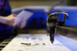
What Is CNC Machining?
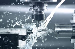
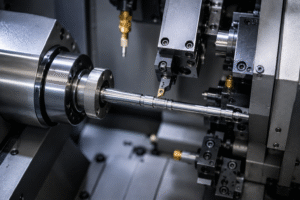
CNC machining is a subtractive manufacturing process where computer-controlled cutting tools remove material from a solid block to create precise parts. It supports a wide range of metals and plastics and is used heavily in aerospace, automotive, medical devices, robotics, electronics, and industrial equipment.
Because the process relies on tool motion along controlled axes, it can achieve tight tolerances, repeatable accuracy, and excellent surface finishes for both prototypes and production runs.
However, the quality of the result depends heavily on CNC Machining Design. The way you define wall thickness, pockets, internal radii, hole geometry, and tolerances determines how efficiently the part can be cut, how stable dimensions will be, and how much the part will cost to manufacture. These decisions directly affect design for machining outcomes.
Main Restrictions of CNC Design
CNC machining is highly capable, but it works within specific geometric and physical constraints. Understanding these early ensures your design for CNC machining is both manufacturable and cost-efficient.
1. Tool Geometry Limitations
The shape of cutting tools directly controls what the machine can and cannot produce. End mills are cylindrical and therefore cannot create perfectly sharp internal corners. They also have limited flute length, which restricts how deep a pocket or slot can be machined without risking tool deflection. These limitations are part of core CNC design requirements.
Why internal corners require radii
Internal corners must include radii that match or exceed the cutter’s radius. Without them, machining slows dramatically or becomes impossible without custom tooling.
Depth limitations from tool length
Longer tools flex under cutting forces, creating tapered walls, poor finishes, and tolerance drift; this becomes severe in hard materials like stainless steel or titanium.
2. Tool Access & Approach
Strong design for CNC machining ensures the cutter can approach features in a direct path. If a feature is blocked, enclosed, or requires angled access, machining becomes more complex and expensive.
Why approach angle matters
Parts that force a tool to reach “around” geometry often require multi-axis machining (4- or 5-axis), which increases cost and setup time.
Access restrictions increase machining time
Restricted access leads to longer toolpaths, additional fixturing, or non-standard tool choices.
3. Part Rigidity & Fixturing Constraints
A part must be held securely during machining. Thin walls, tall unsupported sections, or flexible materials can vibrate during cutting, causing chatter and dimensional variance.
Importance of structural stability
Geometry that lacks stiffness amplifies cutting vibration, leading to poor surface quality and inconsistent tolerance control.
Fixturing influences cost
Complex shapes may require custom fixtures or multiple re-clamps, both of which increase machining time.
4. Material Behavior Limitations
Every material reacts differently under machining forces. Aluminum and brass machine easily, while stainless steel, titanium, and plastics pose additional challenges.
Heat generation and deformation
Hard materials lead to heat buildup and rapid tool wear, while plastics may soften or warp if wall thickness is too thin or feeds are too aggressive.
Material choice affects feature dimensions
Some materials allow thin walls; others require thicker geometry to remain stable during cutting.
CNC Design Guidelines
CNC design guidelines help align CAD intent with real machining capability. These guidelines ensure that geometry remains rigid, tools can reach every feature, and material removal stays efficient. Each subsection below covers a core principle of CNC Machining Design that directly impacts cost, machining speed, and dimensional consistency.
1. Wall Thickness Guidelines
Wall thickness affects rigidity, heat stability, and surface finish. Walls that are too thin tend to vibrate under cutting loads, producing chatter, tapering, and tolerance drift.
Recommended Minimum Wall Thickness
For metals, walls should generally be no thinner than 1.0–1.5 mm in aluminum and 1.5–2.5 mm in stainless steel or mild steel. Plastics require thicker sections, typically 2.0–3.0 mm, to avoid warping or deformation during cutting. These values help maintain part stiffness and support predictable tool engagement.
Material-Specific Adjustments
Different materials require unique considerations. Aluminum supports thinner features because it machines easily, whereas stainless steel and titanium generate heat and cutting force, requiring more robust geometry. Choosing an appropriate thickness greatly improves manufacturability and surface consistency.
Wall Thickness Guidelines
| Material | Minimum Wall | Ideal Wall | Notes |
|---|---|---|---|
| Aluminum (6061/7075) | 1.0 mm | 1.5–2.0 mm | Thin walls vibrate easily |
| Steel (mild/alloy) | 1.5 mm | 2.0–2.5 mm | High cutting forces |
| Stainless Steel (304/316) | 2.0 mm | 2.5–3.0 mm | Heat + deflection |
| Plastics (POM, Nylon, ABS) | 1.5 mm | 2.5–3.0 mm | Warping risk |
| Titanium | 2.0 mm | 2.5–3.0 mm | Slow machining |
Internal Radii & Corners
Internal corners must always include radii because end mills are cylindrical. Attempting sharp internal corners increases machining difficulty and often forces slow toolpaths or custom cutters.
Radii for Efficient Machining
A corner radius equal to or slightly larger than the tool’s radius produces smooth transitions and allows the cutter to maintain speed. Larger radii reduce stress concentration, improve chip evacuation, and help maintain a consistent finish across pocketed areas.
Why Sharp Corners Increase Cost
Sharp internal corners typically require slower machining or additional secondary operations. They also reduce tool life, especially in hard materials, and often lead to chatter marks or surface variations.
Internal & External Radii
Recommended Internal Radii
| Feature | Radius |
|---|---|
| General pockets | R1–R3 mm |
| Deep pockets | R3–R6 mm |
| Internal corners | Tool radius + 0.5 mm |
3. Pockets & Cavities
Pockets influence machining time more than almost any other feature. As depth increases, the rigidity of cutters decreases, creating potential taper and finish issues.
Depth-to-Tool-Diameter Logic
The most efficient machining occurs when pocket depth does not exceed roughly four times the tool diameter. Beyond that limit, tool deflection increases rapidly, slowing machining and reducing accuracy. Wider pockets allow larger tools, which improves stability.
Floor & Corner Requirements
Pocket floors should be designed with consistent thickness, and internal corners should include adequate radii. Avoid creating narrow channels or tall ribs inside pockets, as these geometries are difficult to machine without multiple passes.
-
Holes & Drilling Features
Holes are among the most common CNC features, yet they require thoughtful design to maintain consistency and machinability.
Standard Hole Diameters
Whenever possible, hole diameters should match standard drill bit sizes. Non-standard diameters require reaming, boring, or interpolation, which increases machining time. Depth should ideally remain within six times the hole diameter for predictable chip evacuation and accuracy.
Blind Hole Considerations
Blind holes need a small relief at the bottom to prevent tool stress and burning. Adding a chamfer also improves tapping and thread milling consistency.
-
Threading Requirements
Threads must be designed according to machining constraints to avoid tool breakage and ensure proper engagement.
Ideal Thread Engagement
Most metal threads reach full strength at about 3× the diameter. Extending beyond this adds no functional benefit and increases machining time. Thread milling provides better accuracy but requires more programming.
Material-Based Thread Choices
Soft plastics benefit from threaded inserts, while harder metals support deeper thread engagement with minimal deformation.
-
Tolerances
Tolerances directly affect machining time and cost. Even small deviations from standard machining tolerances require slower toolpaths.
Standard vs. Tight Tolerances
Standard CNC tolerances typically fall within ±0.10 mm for most features, which is suitable for general engineering applications. Tight tolerances below ±0.05 mm should only be applied to functional or mating features to avoid unnecessary machining time and increased inspection requirements.
Typical Tolerance Ranges
| Feature | Standard Tolerance | Tight Tolerance | Notes |
|---|---|---|---|
| General machining | ±0.10 mm | ±0.02–0.05 mm | Depends on machine rigidity |
| Hole diameters | ±0.10 mm | ±0.02 mm | Tighter requires reaming/boring |
| Flatness | 0.1–0.2 mm | <0.05 mm | Large parts harder to control |
| Position (true) | ±0.2 mm | ±0.05 mm | Multi-setup parts vary |
Impact of Material Choice on Tolerance Stability
Harder materials like stainless steel may shift slightly during machining due to heat and stress concentration, while plastics can move more significantly. Understanding the interaction between material and tolerance ensures dimensional stability across production runs.
Because machining generates heat, materials expand differently.
- Aluminum expands quickly → tolerance drift during deep machining
- Stainless steel generates heat → tool wear increases
- Plastics deform → need generous tolerances
Therefore, design engineers must adjust tolerance strategy based on the material’s expansion coefficient.
Get an expert DFM review before machining.
Upload your CAD file and receive engineering feedback within 24 hours, including manufacturability improvements and cost-optimization suggestions.
CNC Machine Setups & Part Orientation
Efficient machining depends on how a part is fixtured and oriented on the machine. Reducing the number of setups improves accuracy, lowers cost, and shortens manufacturing time.
Setup Count & Machining Efficiency
Each additional setup introduces more alignment checks and re-fixturing time. A well-designed part is ideally machinable in a single setup, although two setups are common for features on opposite faces.
Why Fewer Setups Reduce Cost
Fewer setups mean less spindle downtime, no re-zeroing of datums, and lower tolerance stack-up. This improves not only cost efficiency but also dimensional reliability across batches.
How Orientation Affects Tool Access
Orientation determines the possible toolpaths and the angle from which cutters engage material. Good orientation minimizes tool reach, reduces collision risk, and maintains consistent surface quality.
Designing for Straight-Line Tool Access
Features should be positioned so the cutting tool can approach them without obstruction. This minimizes the need for 4-axis or 5-axis machining, which carries added cost.
Datum Strategy for Accuracy
Datums define how a part is referenced during machining. Good datum selection ensures stable clamping, efficient toolpaths, and repeatability across multiple setups.
Maintaining Consistent Reference Surfaces
Critical features should be aligned relative to the most stable surfaces. This ensures tolerance stacking remains predictable and minimizes the risk of alignment errors.
What Is 5-Axis CNC Machining?
5-axis CNC machining allows cutting tools to move along three linear axes (X, Y, Z) and rotate around two additional axes (A and B). This expanded motion enables access to complex geometries that cannot be machined efficiently on standard 3-axis equipment.
For high-performance industries such as aerospace, medical devices, robotics, and precision instrumentation, 5-axis machining provides superior accuracy, reduced fixture complexity, and a smoother surface finish.
Unlike 3-axis machining, which requires multiple setups to reach all faces of a part, 5-axis machining can approach surfaces from virtually any angle. This improves tolerances on multi-face features, reduces machine downtime, and eliminates accumulated alignment errors from repeated re-clamping.
While 5-axis machining offers broader capability, it also introduces higher machine time costs, so designers should leverage it only when the geometry truly demands it.
When 5-Axis Machining Is Required
5-axis machining is ideal for parts with angled pockets, curved features, contoured surfaces, or deeply recessed areas. It enables the machining of undercuts, turbine-style blades, mold components, and complex housings without the need for additional fixturing.
Benefits Over 3-Axis Machining
By maintaining continuous tool engagement at optimal angles, 5-axis machining shortens cycle time, improves finish quality, and reduces the number of machining steps. This results in fewer datums, more consistent tolerances, and better stability for high-performance components.
Cost Considerations of 5-Axis Machining
Although 5-axis machining increases capability, it also increases complexity. The programming time, tooling, and equipment cost are higher, so not all parts benefit from this approach.
When to Stick With 3-Axis
If the part can be accessed in one or two setups on a 3-axis machine without compromising tolerances or finish, 3-axis machining remains the most cost-effective choice. Designers should evaluate whether the added degrees of freedom offer true manufacturing benefit before committing to 5-axis production.
Have a complex, multi-face or contoured part?
Our global CNC network supports advanced 5-axis machining with tight tolerances and production-grade finishes.

CNC Undercuts
An undercut is a recessed or hidden feature that cannot be machined using standard end mills approaching from above. Undercuts are common in consumer products, medical components, and mechanical assemblies where specific mating features or visual profiles are required. While undercuts add functionality, they also introduce complexity and cost because they force machinists to use non-standard tools or multi-axis machining strategies.
When Undercuts Are Needed
Undercuts are used to create features such as O-ring grooves, T-slots, retaining channels, or reverse-facing edges. These geometries provide structural or assembly advantages but cannot be reached with standard vertical toolpaths.
Design Implications
When undercuts are unavoidable, designers should specify clean radii transitions and ensure the geometry is deep enough to accommodate the appropriate tool profile. This prevents tool collision and ensures consistent dimensional accuracy.
Tooling for Undercuts
Machinists use keyseat cutters, lollipop tools, and custom-ground profiles to access recessed geometry. These tools have specific diameter, reach, and clearance limitations.
Tool Access Requirements
Designers must leave enough clearance for the perpendicular portion of the tool to enter the feature. Tight corners or narrow openings often make undercuts impossible to machine without switching to 5-axis equipment.
Cost Impact of Undercuts
Undercuts increase cost because they often require slower toolpaths, multi-axis movements, or dedicated tooling. They also tend to produce more burrs and require secondary finishing.
How to Reduce Cost
If possible, replace undercuts with chamfers, open profiles, or angled surfaces. Simplifying the geometry often makes the part easier to machine without sacrificing performance.
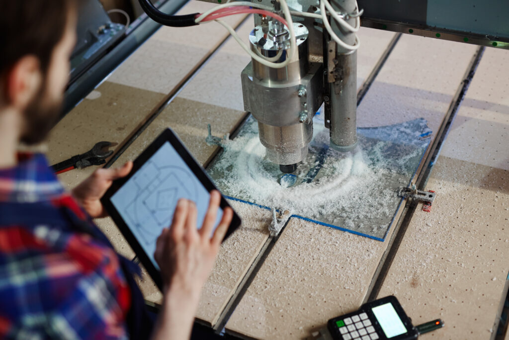
Drafting a Technical Drawing
A technical drawing plays a critical role in the design for CNC machining process because it communicates requirements that a 3D model alone cannot express. While modern CNC workflows rely heavily on CAD data, machinists still depend on 2D drawings for dimensioning, tolerances, notes, thread specifications, and inspection guidance.
A well-prepared drawing reduces ambiguity, shortens review cycles, and ensures that the final machined part matches design intent.
Why Technical Drawings Are Still Essential
Although CAM software extracts toolpaths directly from CAD geometry, key manufacturing decisions—such as how surfaces should be measured, how features relate to each other, and which tolerances matter most—must be documented in a drawing. Drawings signal to machinists which dimensions are critical-to-function and which can follow standard machining capability.
Communicating Functional Requirements
Drawings help define datums, positional relationships, surface finish notes, and GD&T symbols. These details provide clarity to machinists and quality teams, ensuring that inspection methods align with design intent.
Dimensioning for design in CNC Machining
Dimensions should be logical, consistent, and based on functional rather than cosmetic requirements. Over-dimensioning a drawing can introduce unnecessary complexity, while under-dimensioning may leave machinists guessing.
Best Practices for Dimension Placement
Place dimensions on the view where the feature is most visible. Use aligned datums to improve machinability and reduce tolerance stacking issues. Avoid redundant dimensions and reference unnecessary edges.
Tolerance Notation & GD&T
Tolerances indicate the acceptable range of variation for critical dimensions. GD&T defines how features must relate to one another in terms of location, flatness, orientation, and form.
Choosing the Right Symbols
Use GD&T symbols like position, flatness, and parallelism only where function demands higher accuracy. Overuse inflates cost and slows machining due to repetitive finishing passes.
Threads, Surface Finishes & Notes
Drawings must specify thread type, pitch, engagement depth, and any finishing requirements such as anodizing or bead blasting.
Essential Notes for Machinists
Keep notes clear and concise. Specify finish only when necessary. Identify break-edges if chamfers are not explicitly dimensioned. Indicate any special inspection instructions when required.
Best Practices for CNC Machining
Strong CNC machining design comes from aligning engineering intent with manufacturability. The best practices below summarize how to create efficient, accurate, and cost-effective parts while minimizing machining difficulties.
Design for Stable Machining
Rigid geometry supports better cutting behavior. Features like very thin walls, tall unsupported ribs, and narrow channels reduce machining efficiency.
Structural Stability Matters
Parts with balanced proportions and consistent cross-sections produce smoother toolpaths and achieve tighter tolerances with less rework.
Use Tolerances Strategically
Not every feature needs tight tolerances. Reserve precision for mating features, bearing interfaces, and functional surfaces.
Avoid Over-Tolerancing
Unnecessary precision increases tool wear and slows toolpaths. Target standard tolerances everywhere that is not function-critical.
Choose Materials Wisely
Material selection affects tool wear, achievable tolerances, and machining time. Aluminum is fast and reliable; stainless steel and titanium require slower machining; plastics deform under heat.
Material Behavior Changes Geometry Rules
Hard metals require thicker walls and larger radii. Plastics demand balanced wall thickness to avoid warping. Choosing the right material early reduces redesign cycles.
Simplify Geometry Whenever Possible
Simple shapes machine faster, cost less, and result in more repeatable quality. Features such as deep pockets, blind channels, and tight internal corners add complexity without always adding functional value.
Minimize Deep or Narrow Features
Machining tools struggle in confined areas. Reducing depth or widening access improves speed and accuracy.
Align Designs With Standard Tools
Standard end mills, drills, and taps offer the best balance of accuracy and cost. Non-standard tool sizes require custom programming and specialized tooling.
Tool Standardization Improves Efficiency
Using common diameters, radii, and thread types reduces machining time, tooling cost, and potential lead-time delays.
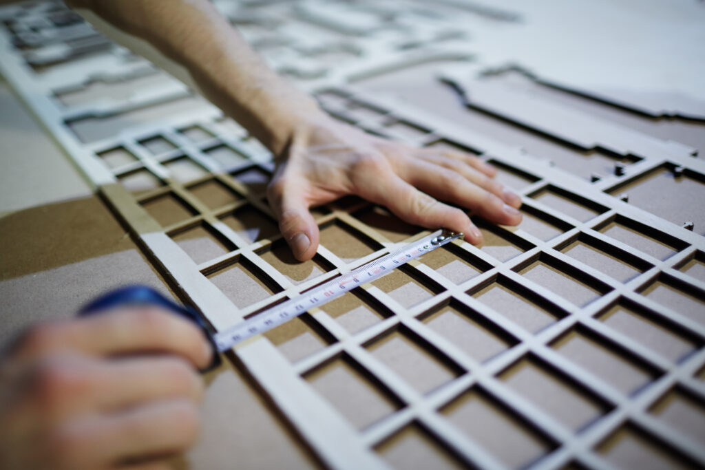
Plan for Inspection
Parts should be designed so that machinists and inspectors can measure critical dimensions easily.
Measurement Simplicity Improves Quality
Flat, accessible reference surfaces ensure predictable inspection outcomes and consistent production results.
Bring your design to life with precision CNC machining.
Upload your CAD file to receive a 24-hour manufacturing review, optimized DFM feedback, and a fast, accurate quotation.
Frequently Asked Questions
What is the ideal wall thickness for CNC machining?
The ideal wall thickness depends on the material. Aluminum walls should typically be between 1.0–1.5 mm, while stainless steel benefits from 1.5–2.5 mm for stability. Plastics require 2.0–3.0 mm to prevent thermal distortion. Choosing the proper thickness ensures rigidity, predictable tolerance control, and a smoother surface finish.
How do internal radii affect CNC machining?
Internal radii must match the cutter’s geometry. Sharp corners slow machining or require custom tooling. Providing a radius equal to—or larger than—the tool radius allows continuous toolpaths, reduces heat buildup, and improves chip evacuation, making machining more efficient and cost-effective.
Why are deep pockets expensive to machine?
Deep pockets require long tools, which flex more and cause chatter, taper, or poor finishes. This forces machinists to slow feeds and speeds, add more finishing passes, or use specialized tooling. Keeping pocket depth within 4× the tool diameter minimizes complexity and reduces cycle time.
When should I use tapped vs. milled threads?
Tapped threads are fast and cost-effective but less flexible in tight spaces or harder materials. Thread milling offers greater precision and better control over thread quality but increases cycle time. Choose based on tolerance requirements, material hardness, and thread diameter.
What tolerance can CNC machines achieve?
Standard CNC machining typically achieves ±0.10 mm without difficulty. Features requiring higher precision may reach ±0.02–0.05 mm, but tighter tolerances increase machining time, tool wear, and inspection requirements. Tolerances should align with functional requirements only.
Do all CNC machined parts need technical drawings?
Not always, but technical drawings are essential for communicating datums, tolerances, GD&T, surface finishes, threads, and inspection requirements. They help machinists interpret functional intent and avoid misunderstandings not visible in the 3D model.
When should I choose 5-axis machining?
Use 5-axis machining when the geometry includes angled pockets, curved surfaces, deep undercuts, or multiple faces requiring precise alignment. If the part can be machined in one or two setups on a 3-axis machine, 3-axis machining typically remains the most cost-effective choice.
Read More
CNC Machining Services India
PRECISION CNC MACHINING SERVICES • MADE IN INDIA CNC Machining Services India From Prototype to [...]
Aug
CNC Machining Supplier USA | Precision CNC Machined Parts from India
Trusted CNC Machining Supplier for USA | ISO Certified Manufacturing in India CNC Machining Supplier [...]
Precision Cylindrical Grinding Services
Precision Manufacturing • Built in India • Delivered Globally Precision Cylindrical Grinding Services Manufyn delivers [...]